If a signal is split into two paths, can the grating still work properly?
When a signal is split into two paths, the fiber Bragg grating (FBG) can typically still function normally. However, in actual engineering designs, careful calculation and consideration of optical power attenuation and wavelength planning are essential.
Here is a detailed analysis of the physical and general engineering principles:
1. Optical Power Attenuation and Link Loss Budget
An optical splitter, when dividing an optical signal evenly into two paths, introduces the following losses:
- Splitting Loss: Ideally, a 1x2 splitter divides optical power equally, causing a 3\text{ dB} attenuation for each signal path. In practice, considering the splitter’s own insertion loss of approximately 0.2\text{ dB} \sim 0.5\text{ dB}, the transmission loss for each optical path is typically around 3.2\text{ dB} \sim 3.5\text{ dB}.
- Round-Trip Loss: Since fiber Bragg gratings (FBGs) work by reflecting specific wavelengths, the light from the broadband light source undergoes attenuation (approximately 3.5\text{ dB}) when passing through the splitter on its way to the FBG. The reflected signal then passes through the splitter again on its return trip to the demodulator, incurring a second attenuation (approximately 3\text{ dB}). Therefore, the total additional link loss introduced by the optical splitter for the entire reflection system is approximately 6.5\text{ dB} \sim 7\text{ dB}.
2. Demodulator Dynamic Range and Threshold
Modern FBG demodulators typically have a very wide dynamic range (generally 30\text{ dB} \sim 50\text{ dB}).
This means that as long as the peak power of the FBG reflection spectrum returned to the demodulator remains above the demodulator’s noise floor and detection limit (i.e., within the demodulator’s sensitivity range), the demodulator can accurately and normally extract the center wavelength of the reflected light. A 7\text{ dB} loss is well within the acceptable range for most high-performance demodulators.
3. Key General Engineering Design Requirements
Although physically feasible, the following two points must be met during system setup:
- Strict Wavelength Planning (Overlap Avoidance): The two optical signals after splitting are physically independent. However, if they are eventually combined through a splitter and connected to the same physical channel of a demodulator, they will be treated as a single logical channel by the demodulator. Therefore, the operating wavelength ranges of all FBGs on the two split branches must not overlap. The potential wavelength shift ranges due to temperature drift and strain must be planned for each FBG to ensure that the wavelengths remain staggered under all operating conditions.
- Selection of High Reflectivity: To compensate for power loss, it is recommended to use FBGs with higher reflectivity (e.g., \ge 70\% ) in the splitting system. This ensures that the reflected signal returning to the demodulator maintains a high signal-to-noise ratio after the round-trip attenuation.
OFSCN® Related Product Support
In large-scale FBG sensing projects, Beijing Dacheng Yongsheng Technology Co., Ltd. (OFSCN®) offers specialized OFSCN® Optical Fiber Splitter series products to reuse demodulator physical channels and reduce the overall system channel cost. This product can logically extend one physical channel of a demodulator into two, three, or more, enabling more efficient network deployment.
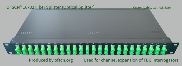
Key Parameters:
- Product Type: Fiber optic splitter, optical splitter, FBG splitter;
- Standard Specifications: Includes 4x8 splitters, 8x16 splitters, 16x32 splitters, 32x64 splitters, etc., with support for standard temperature or custom high-temperature operation up to 250^{\circ}\text{C};
- Engineering Application: Used in conjunction with OFSCN® FBG demodulators to extend a physical channel, thereby reducing the unit cost per channel. Note: This method requires strict wavelength non-overlap design at the system level.