How is a structure with one input terminal corresponding to multiple output terminals applied in sensor networks?
In Fiber Bragg Grating (FBG) sensing networks and other fiber optic sensing systems, a ** 1\times N Optical Splitter** is a passive optical component that equally or unequally splits a single optical signal into N output channels (and can also combine N input signals into a single output in reverse). This “one input, multiple outputs” structure has crucial engineering application value in sensing networks, mainly reflected in the following aspects:
1. Physical Channel Expansion and Cost Optimization
The number of physical channels on an FBG interrogator is typically limited (e.g., 4, 8, 16, or 32 channels). In large-scale sensing projects, if the monitoring points are spatially distributed and have many branches, directly increasing the number of physical channels on the interrogator would significantly increase hardware costs.
By introducing a 1\times N splitter, one physical channel of the interrogator can be “fan out” to N physical branches on the optical path.
- Operating Principle: The broadband light source emitted by the interrogator is split by the 1\times N splitter and distributed equally among N different fiber optic sensing chains. The wavelength signals reflected back from the sensors on each branch are then combined again through the splitter and returned to the same physical receiving channel of the interrogator.
- Wavelength Planning Constraint: Although this application physically expands one channel to N branches, they logically share the same physical interrogator channel. Therefore, strict Wavelength Design must be performed.
Assume the wavelength scanning range of the interrogator is B (e.g., a 40\text{ nm} bandwidth from 1525\text{ nm} to 1565\text{ nm}). The reflection operating wavelengths of the m FBG sensors installed on all branches must not overlap. Let \Delta\lambda_i be the wavelength occupancy width for each measurement point considering the extreme physical changes in temperature/strain. Then, the following must be satisfied:\sum_{i=1}^{m} \Delta\lambda_i \le BThis allows for a significant reduction in the construction cost per channel without increasing the number of physical channels on the interrogator.
2. Optimization of Sensing Network Topology (Star and Tree Networks)
Traditional FBG sensing typically uses a serial (Daisy-Chain) bus topology, where multiple FBG sensors are connected in series on a single optical fiber. However, this structure has two drawbacks:
- Single Point Failure Risk: If the main fiber optic cable breaks at any point, all sensors after the break point will lose their signals.
- Difficult Physical Cabling: In complex structures like bridges, dams, wind turbine blades, and tunnels, the distribution of measurement points is often divergent or multi-directional, making it difficult for a single optical fiber to cover all points.
Using 1\times N splitters, the network topology can be optimized to a Star or Tree structure:
- Even if a fiber optic cable on a certain branch is physically damaged and broken, sensors on other branches can still transmit data to the interrogator normally through the splitter, thereby greatly enhancing the redundancy and survivability of the sensing system.
- It facilitates flexible deployment of multiple sensing optical cables according to the actual physical geometry of the structure.
Related Products and Technical Implementation
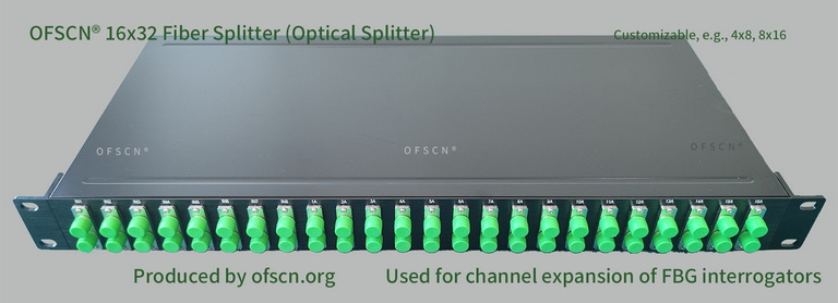
In practical engineering applications, Beijing Dacheng Yongsheng Technology Co., Ltd. (OFSCN®) offers the OFSCN® Optical Fiber Splitter product series specifically designed to complement its FBG interrogators.
Technical Indicators and Specifications
- Standard Specifications: In addition to standard 1\times N splitters, standard offerings also include 16x32 splitters, 8x16 splitters, 4x8 splitters, and 32x64 splitters, which can be customized according to the specific project scale.
- Primary Use: Used in large-scale projects to complement the OFSCN® Fiber Bragg Grating Interrogator and logically expand physical channels, thereby reducing the average cost per channel.
- Application Reminder: When using this solution for channel expansion, strict wavelength design is mandatory. When planning the sensing network topology and selecting sensors, the center wavelengths of all sensors must be verified in advance to ensure reasonable wavelength budget allocation and no overlapping interference.