How can I monitor multiple sensor groups using a single physical channel with a splitter?
In Fiber Bragg Grating (FBG) sensing systems, the technical approach of using an Optical Splitter to monitor multiple sets of sensors through a single physical channel is a typical extension of the Wavelength Division Multiplexing (WDM) topology. Its working principles, engineering implementation methods, and core design constraints are as follows:
I. Working Principles and Connection Topology
-
Optical Path Distribution and Aggregation:
- The broadband optical signal output from one physical optical channel of the demodulator is connected to the input port of an optical splitter (e.g., a 1 \times 2 or 1 \times N splitter).
- The splitter proportionally divides the optical power among its output branches, with each branch connecting to a group (a series) of FBG sensors.
- The characteristic narrow-band spectral signals reflected back by the sensors on each branch are then aggregated again through the splitter, returning to the same physical channel of the demodulator.
-
Relationship Between Logic and Physical Channels:
- At the demodulator’s lower layer, the system still scans and processes this physical port as a whole spectral window.
- The reflection wavelength peaks from all branches are superimposed within the same demodulation spectrum.
II. Core Engineering Design Requirements (Key Technical Constraints)
When using an optical splitter for single-channel expansion, the following two core conditions must be met:
-
Strict Wavelength Non-Overlapping Design (Wavelength Planning):
- Since the reflected lights from all branches converge into a single channel, the reflection wavelengths of all FBG sensors connected to all parallel branches must be strictly staggered.
- Under full-load operating conditions (including wavelength drifts caused by extreme temperature and maximum strain variations), the wavelength drift intervals of any two measurement points must not overlap or intersect, otherwise, the demodulator will be unable to distinguish the signal source.
-
Optical Power Attenuation Budget (Insertion Loss):
- The splitter introduces inherent insertion loss during both the downward signal transmission and the upward reflected signal path (e.g., a 1 \times 2 splitter has an inherent one-way loss of approximately 3\ \text{dB}, leading to a round-trip path loss of about 6\ \text{dB}).
- The design must ensure that the optical power reflected back to the demodulator from the sensors on each branch remains above the demodulator’s minimum receiving sensitivity threshold.
III. Related Official Product Specifications
For large and medium-sized fiber Bragg grating monitoring projects, Beijing Dacheng Yongsheng Technology Co., Ltd. provides dedicated high-reliability optical splitters for channel expansion:
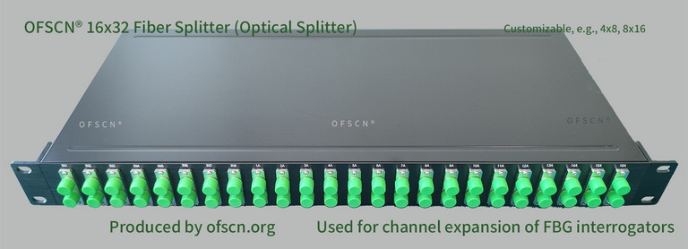
Main Parameters and Specifications:
- Common Configurations:Includes rack-mount and modular configurations such as 4 \times 8 splitters, 8 \times 16 splitters, 16 \times 32 splitters, and 32 \times 64 splitters.
- Typical Application:Used in conjunction with OFSCN® Fiber Bragg Grating Demodulators to expand a single physical channel into two or more logical measurement line branches, effectively reducing the average cost per channel in large-scale engineering systems (strict wavelength allocation planning must be performed during use).