External strain of 100 units, how much can the internal grating sense? Where is the loss?
I. What is Strain Transfer Efficiency?
In Fiber Bragg Grating (FBG) strain sensing technology, Strain Transfer Efficiency refers to the proportion of the actual strain generated by the measured substrate (external structure) that is ultimately transmitted through the adhesive, protective sheath, fiber coating, and other media layers via shear, reaching the fiber core (Fiber Bragg Grating).
In mechanical models, it is typically represented by the transfer coefficient k (or \alpha):
\alpha = \frac{\varepsilon_f}{\varepsilon_s}
Where:
- \varepsilon_f is the strain actually sensed and measured by the Fiber Bragg Grating (internal core).
- \varepsilon_s is the true strain occurring in the measured substrate (external).
II. If the external structure is stretched by 100 units, how much can the internal grating sense?
If the external structure is stretched by 100 units (e.g., 100\ \mu\varepsilon), the amount sensed by the internal Fiber Bragg Grating depends entirely on the sensor’s packaging stiffness, installation method, anchoring length, and interface shear characteristics:
-
Ideal Conditions (Approaching 100%):
With high-stiffness, adhesive-free metallized packaging, or when bare fibers are directly fused/anchored to the substrate with high rigidity, the strain transfer coefficient can reach 95\% to 99\%. In this case, an external stretch of 100 units would result in the internal grating sensing 95 to 99 units. -
Standard Adhesive or Soft Sheath Packaging (Reduced to 50% ~ 80%):
If the sensor internally uses soft epoxy resin filler or has a thick soft plastic sheath around the fiber, the transfer efficiency will be significantly reduced. An external stretch of 100 units might only be sensed as 50 to 80 units internally. -
Insufficient Anchoring Length (Efficiency Plummets):
If the sensor’s bonding or anchoring length is too short, preventing a stable strain field from being established at the center due to shear slip at the ends, the transfer efficiency can drop below 30\%.
III. Where specifically does the loss (shear lag) occur?
As strain is transferred from the outermost layer (measured substrate) to the innermost layer (fiber core), it must pass through multiple heterogeneous interfaces. The loss primarily occurs in the elastic shear transfer (mechanically known as Shear Lag Effect). The losses are mainly distributed across the following four locations:
-
Shear Elastic Loss in the Adhesive Layer:
This is the primary source of loss for surface-mounted sensors. The external substrate (e.g., steel structure, elastic modulus approx. 200\text{ GPa}) and the fiber (quartz, elastic modulus approx. 72\text{ GPa}) are very stiff, while the intermediate adhesive (e.g., conventional epoxy resin, elastic modulus typically only 2 \sim 4\text{ GPa}) is very soft. Due to its extremely low elastic modulus, the adhesive layer undergoes severe shear deformation when transmitting tensile force, consuming significant energy and failing to fully convert it into tensile strain in the fiber. -
Shear Absorption by the Fiber Coating Layer:
Standard communication fibers have an acrylate coating layer, which is very soft and absorbs a significant portion of the shear force. Using fibers with acrylate coatings directly for strain sensing results in substantial strain loss at the coating interface. Switching to a hard polyimide coating layer significantly reduces this loss. -
Stiffness Inhibition and Mismatch of Sensor Packaging Material:
If the sensor has a thick stainless steel or polymer protective outer sheath, there will be shear slip between the sheath and the fiber. Furthermore, the axial stiffness of the packaging tube itself can cause a ‘Local Stiffening Effect’ on the relatively soft substrate, conversely hindering strain development in the substrate within the sensing segment, leading to measurement loss and distortion. -
End Effects and Insufficient Bonded Length:
According to the shear lag mechanical model, strain transfer is not uniform along the entire length. At the end of the bonded segment (or packaging end), shear force is maximal, but the axial strain transfer efficiency is 0. Only after extending a certain distance towards the center (known as the effective transfer length) can the transfer efficiency increase and reach a stable value. If the sensor is too short or the bonding length is insufficient, the strain is not fully transferred into the fiber before the end is reached, causing end-face loss.
IV. How to reduce loss and achieve efficient strain transfer?
In optical engineering and strain sensor design, the following measures are typically taken to reduce strain loss:
- Miniaturization and Thin-Walling:** Reducing the outer diameter and wall thickness of the packaging to decrease the sensor’s own stiffness, making it deform more easily in sync with the substrate.
- High-Modulus Adhesives or Adhesive-Free Metallized Anchoring:** Using adhesives with extremely high shear modulus, or achieving adhesive-free rigid connection through full metal welding or fusion sealing.
- Selection of Special Hard-Coated Fibers:** For example, using polyimide fibers with extremely thin, ultra-hard coatings, which generate almost no shear loss from the coating layer.
Beijing Dacheng Yongsheng Technology Co., Ltd. (OFSCN®) has conducted in-depth optimizations in materials and structures for various precision strain measurement and control scenarios, designing multiple fiber strain sensor products with high transfer efficiency:
1. OFSCN® Alloy Tube Packaged Fiber Bragg Grating strain sensor
This sensor utilizes an elastic alloy tube for micro-packaging of the Bragg grating, with a product outer diameter of only \le 1.1\text{ mm}. The extremely thin tube diameter and high elastic modulus alloy substrate minimize shear lag and eliminate strain transfer resistance, making it suitable for various precision tensile and strain monitoring applications.


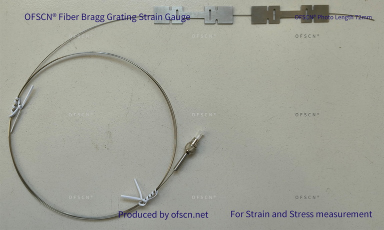
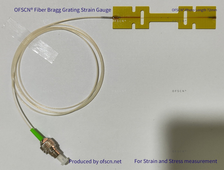
2. OFSCN® Fiber Bragg Grating Strain Gauge
This strain gauge features an I-beam-like structure with a substrate made of ultra-thin stainless steel or aluminum alloy. It supports direct spot welding or surface mounting with a thin adhesive layer. This flattened, close-contact design minimizes the thickness of the intermediate adhesive layer, thereby reducing strain transfer loss to an extremely low level.
3. OFSCN® 200°C OFDR Micro All-Metal Strain Sensor
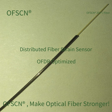
Specially designed for high spatial resolution Distributed Optical Frequency Domain Reflectometry (OFDR) strain measurements. The outer diameter is reduced to 0.6\text{ mm}, and internally it uses ultra-hard polyimide specialty fiber by default. This not only offers high-temperature resistance but also minimizes fiber coating shear loss to the physical limit, providing extremely high strain response consistency.