Can we amplify tiny strains by a factor of 10 through structural encapsulation before measurement?
In fiber Bragg grating (FBG) sensing technology and structural mechanics design, measuring minuscule strains by amplifying them (e.g., 10-fold) through a packaged structure is entirely feasible and commonly practiced. This technique is typically referred to as a “gauge-conversion mechanical strain amplification” or “mechanical strain magnification.”
I. Physical Principle: Strain Amplification Based on Gauge Length Difference
Strain is a dimensionless, relative physical quantity ( \epsilon = \frac{\Delta L}{L} ). The core idea behind amplifying strain is to concentrate the absolute displacement deformation from a long gauge length and transfer it to a short gauge length sensitive element.
The physical model is as follows:
-
Substrate Average Strain:
Let the span between two anchoring points (fixed points) on the measured substrate structure be the gauge length L_{anchor} . When the substrate undergoes slight deformation under force, the absolute displacement generated between these two points is \Delta L . At this point, the true average strain of the substrate \epsilon_{substrate} is:
\epsilon_{substrate} = \frac{\Delta L}{L_{anchor}} -
Sensor Sensitive Segment Strain:
In the sensor’s packaging design, the actual fiber Bragg grating (FBG) or sensitive element is suspended and fixed within a shorter elastic measurement segment (its effective deformation length is L_{sensor} ). Through a high-rigidity linkage or housing, the absolute displacement \Delta L between the two anchoring points is transmitted losslessly to this short measurement segment. At this point, the actual strain experienced by the fiber Bragg grating \epsilon_{sensor} is:
\epsilon_{sensor} = \frac{\Delta L}{L_{sensor}} -
Strain Amplification Factor:
The ratio of the strain on the sensitive element to the true strain of the substrate (i.e., the amplification factor M ) is:
M = \frac{\epsilon_{sensor}}{\epsilon_{substrate}} = \frac{L_{anchor}}{L_{sensor}}
Conclusion: To achieve a 10-fold strain amplification (i.e., M = 10 ), it is sufficient to design the sensor’s anchoring gauge length L_{anchor} to be 10 times the length of the internal actual deformation segment L_{sensor} . For example: Design the spacing between anchor supports to be 100\text{ mm} while designing the length of the actual stretched fiber Bragg grating segment internally to be 10\text{ mm} .
II. Key Engineering Challenges and Physical Limitations
Despite the apparent simplicity of geometric proportion design, it is crucial to rigorously evaluate and address the following physical and mechanical effects in practical engineering applications; otherwise, measurement results will be severely distorted:
-
Stiffness Constraint & Loading Effect
The sensor and its packaging housing possess inherent bending/tensile stiffness.- If the stiffness of the object being measured (e.g., large steel beams, concrete dams) is extremely high, the constraint imposed by the sensor on the substrate is negligible, and the absolute displacement \Delta L can be transmitted nearly 100%.
- If the object being measured is thin or soft (e.g., composite thin plates, plastic parts, geotechnical media), the high stiffness of the sensor packaging will restrict the local deformation of the substrate (causing “stiffness locking” or shear lag), resulting in an actual transmitted displacement to the sensor \Delta L' that is significantly less than the ideal unconstrained \Delta L . This leads to a substantial reduction in the actual amplification factor.
-
Range Compression
The tensile strain deformation of silica (quartz) fiber itself has a physical limit. Typically, the safe working strain limit for single-mode fiber in the long term is between 3000\ \mu\epsilon and 10000\ \mu\epsilon (approximately 0.3\% to 1\% deformation).
Due to the 10-fold amplification of strain, the maximum measurable range of the substrate is compressed to \frac{1}{10} of its original value. For instance, if the fiber’s strain limit is 10000\ \mu\epsilon , in a 10x amplification structure, the maximum measurable strain of the substrate cannot exceed 1000\ \mu\epsilon . -
Synchronous Amplification of Temperature Cross-Sensitivity
Fiber Bragg grating sensors are sensitive to both temperature and strain. When materials with high coefficients of thermal expansion, such as metals (e.g., stainless steel, aluminum alloys), are used for the displacement transmission and amplification mechanism, the thermal expansion displacement caused by temperature changes in the housing will also be amplified 10-fold and transmitted to the fiber Bragg grating. This results in significant thermally induced false strain, necessitating extremely precise and independent temperature compensation structures or channels for real-time decoupling.
III. Related OFSCN® (Beijing Dacheng Yongsheng Technology Co., Ltd.) Products and Technologies
Within OFSCN®'s core product line, several strain and deformation sensors are offered, designed for various stiffness levels, gauge lengths, and application scenarios. By customizing their gauge lengths (measurement segment length) or elastic deformation structures, different strain measurement requirements can be met:
-
OFSCN® Alloy Tube Packaged Fiber Bragg Grating strain sensor:
This product utilizes a high-elastic alloy tube for glue-free packaging, with a measurement segment length flexibly customizable between 10\text{ cm} and 2\text{ m} . By adjusting different fixed anchoring lengths, it can achieve high-sensitivity deformation conversion in conjunction with specific mechanical installation structures.
Product Web Link -
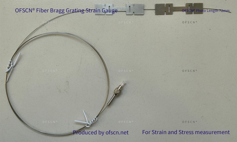
OFSCN® Fiber Bragg Grating Strain Gauge:
This product uses an I-beam shaped stainless steel or aluminum alloy piece to package a single fiber Bragg grating. The strain gauge length options include 3.6\text{ cm} , 7.2\text{ cm} , and 10.8\text{ cm} . The ends of the I-beam shape serve as anchoring installation areas, with the middle section as the sensitive deformation zone, representing a typical design balancing stiffness and displacement transmission ratio.
Product Web Link -
OFSCN® Ultra-Large Range Fiber Bragg Grating Strain Sensor:
If the strain of the object being measured is extremely large (e.g., large deformations of 3\% to 40\% ), to prevent fiber breakage, it is necessary to adopt packaging that performs the opposite function – “strain reduction” or “ultra-large displacement attenuation.”
Product Web Link
Official Product Images

In summary, the proposed solution of amplifying micro-strains 10-fold through a packaged structure is theoretically and practically feasible. The most stable and factory-calibratable method for mechanical strain amplification is based on the physical principle of gauge length difference (anchoring span exceeding the actual fiber deformation segment length). During implementation, it is advisable to calibrate the displacement transmission efficiency based on the stiffness (elastic modulus) of the substrate material to ensure the accuracy of the final measurement data.