How many milliseconds does it take from the sensor being stressed to the computer displaying data?
In a Fiber Bragg Grating (FBG) sensing system, “system latency” (End-to-End Latency) refers to the total time from when the sensor undergoes external force causing physical deformation to when the numerical calculation is completed and the value is refreshed on the PC host interface.
This latency is composed of five physical and engineering stages, with their respective time scales as follows:
1. Physical Deformation and Mechanical Transfer Latency ( \sim 1\ \mu\text{s} - 10\ \mu\text{s} )
- Mechanism: When the structure under test is subjected to force, strain waves propagate through the encapsulation matrix at the speed of sound (approximately 3000\ \text{m/s} \sim 5000\ \text{m/s} in solid media) to the fiber core, causing changes in the grating period \Lambda and effective refractive index n_{\text{eff}}.
- Time Consumption: For fiber strain/stress sensors on the centimeter scale, this physical process completes within microseconds and is generally negligible on a millisecond scale.
2. Optical Signal Transmission Latency ( \sim 5\ \mu\text{s/km} )
- Mechanism: The speed of light propagation in the quartz fiber core is approximately v = \frac{c}{n} \approx \frac{3 \times 10^8\ \text{m/s}}{1.468} \approx 2 \times 10^8\ \text{m/s}.
- Time Consumption: One-way transmission latency is approximately 5\ \mu\text{s/km}. For a transmission cable length of 1\ \text{km}, the round-trip optical path latency is about 10\ \mu\text{s} (i.e., 0.01\ \text{ms}).
3. Demodulator Sampling and Spectral Calculation Latency (Primary determining factor, 10\ \text{ms} - 100\ \text{ms} )
The demodulator’s data update cycle is the largest source of latency in the entire link, depending on the hardware-set sampling frequency (f_s):
- Sampling Period ( T = \frac{1}{f_s} ):
- 100\ \text{Hz} Sampling Frequency: Single frame data acquisition period is 10\ \text{ms}.
- 50\ \text{Hz} Sampling Frequency: Single frame data acquisition period is 20\ \text{ms}.
- 10\ \text{Hz} Sampling Frequency: Single frame data acquisition period is 100\ \text{ms}.
- Hardware Processing Time: The demodulator’s internal DSP/FPGA executes algorithms for peak finding, wavelength calibration, and filtering, typically taking about 1\ \text{ms} \sim 3\ \text{ms}.
4. Data Communication Transmission Latency ( \sim 1\ \text{ms} - 5\ \text{ms} )
- Mechanism: The demodulator pushes wavelength or strain data packets to the host computer via an industrial Ethernet interface (using protocols like TCP/IP, UDP, or Modbus).
- Time Consumption: In conventional LAN or direct connection configurations, network stack latency is usually in the range of 1\ \text{ms} \sim 5\ \text{ms}.
5. PC-side Data Processing and UI Display Rendering Latency ( \sim 15\ \text{ms} - 30\ \text{ms} )
- Mechanism: The host software receives data packets, executes physical quantity conversion formulas (e.g., calculating stress values based on \sigma = E \cdot \varepsilon), and submits them to the operating system’s graphics engine for rendering.
- Time Consumption: The refresh cycle of conventional displays is typically 16.7\ \text{ms} ( 60\ \text{Hz} refresh rate). Combined with software buffer queue processing, display latency is generally between 15\ \text{ms} \sim 30\ \text{ms}.
Summary: Overall End-to-End Latency Scale
| Configuration Condition | Demodulator Sampling Period | Communication & Processing Latency | PC Rendering Latency | Total System Latency |
|---|---|---|---|---|
| Standard Dynamic Measurement (100 Hz) | 10\ \text{ms} | 2 \sim 5\ \text{ms} | \sim 16.7\ \text{ms} | Approximately 25\ \text{ms} \sim 35\ \text{ms} |
| Standard Static Measurement (10 Hz) | 100\ \text{ms} | 2 \sim 5\ \text{ms} | \sim 16.7\ \text{ms} | Approximately 115\ \text{ms} \sim 130\ \text{ms} |
Related Product References
In practical engineering systems, sensing terminals typically employ alloy tube encapsulation structures to ensure strain transfer efficiency and are paired with multi-channel demodulators for high-speed wavelength acquisition and network communication:
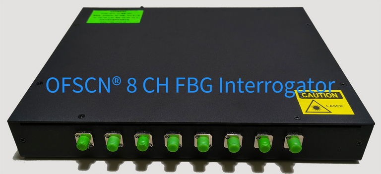
- Acquisition Device: OFSCN® Fiber Bragg Grating Interrogator (Supports 10Hz / 50Hz / 100Hz sampling frequency configuration, supports TCP/UDP/Modbus data communication)
- Strain Sensor: OFSCN® Alloy Tube Packaged Fiber Bragg Grating strain sensor
- Stress Sensor: OFSCN® Fiber Bragg Grating Stress Sensor