Why can some machines see changes of 1 picometer, while others can only see 10 picometers?
In Fiber Bragg Grating (FBG) demodulation technology, what users typically refer to as “how many picometer changes can be seen” corresponds to the Wavelength Resolution or Minimum Measurable Wavelength Change of the demodulator in engineering and metrology.
The difference in resolution between various devices, such as 1\ \text{pm} versus 10\ \text{pm} (or even higher or lower), is primarily determined by the device’s optical architecture, hardware detection principles, internal calibration mechanisms, and signal-to-noise ratio (SNR). The main distinctions lie in the following physical and engineering dimensions:
1. Fundamental Differences in Optical Demodulation Principles and Hardware Architectures
Mainstream FBG demodulators on the market typically adopt one of the following three optical architectures, whose physical spectral separation mechanisms directly limit wavelength resolution capabilities:
- Spatial Dispersion Grating + Linear Array Detector (Spectrometer / Linear Array CCD/CMOS):
- Principle: Broadband light from a source illuminates the sensor. The reflected light is dispersed spatially by a fixed diffraction grating and projected onto the pixels of a linear array CCD or CMOS.
- Resolution Bottleneck: Limited by the physical pixel size of the detector and the optical focal length. For instance, within a typical 40\ \text{nm} working bandwidth, if a 2048-pixel detector is used, the spectral interval per pixel is approximately 20\ \text{pm}. Even with sub-pixel interpolation using Gaussian fitting or centroid algorithms, and considering optical aberrations, stray light, and pixel crosstalk, the reliable wavelength resolution is generally in the range of 5\ \text{pm} \sim 10\ \text{pm}.
- Fiber Fabry-Pérot Tunable Filter (FFP-TF):
- Principle: Precisely drives minute changes in the cavity length of a Fiber Fabry-Pérot cavity using piezoelectric ceramics (PZT), enabling periodic scanning of a narrow transmission peak across the measurement band.
- Resolution Advantage: FFP-TF filters have narrow transmission spectral linewidths. Combined with high-precision digital-to-analog converters (DACs) that control the PZT with microvolt-level voltage, they can achieve spectral scanning with very small steps, generally achieving resolutions of 1\ \text{pm} or even better.
- Tunable Laser Source (TLS) Scanning:
- Principle: Uses a laser with an extremely narrow linewidth (typically less than a few picometers or even kilohertz level), high monochromaticity, and high power density to scan the spectrum point by point.
- Resolution Advantage: Fine wavelength stepping without relying on the integral fitting of broadband reflection spectra, easily achieving high resolutions of 1\ \text{pm} or 0.1\ \text{pm}.
2. Real-time Optical Reference and Closed-Loop Calibration Mechanisms
- Devices with High-Precision Internal References (\le 1\ \text{pm}):
High-resolution demodulators typically incorporate physical optical wavelength references, such as gas absorption cells (e.g., acetylene or hydrogen cyanide cells) or highly temperature-stable fixed Fiber Fabry-Pérot etalons. During each spectral scan cycle, the device performs real-time comparison against known physical absorption peaks to dynamically compensate for nonlinear errors caused by PZT hysteresis, creep, temperature drift, and mechanical vibrations. - Open-Loop or Factory Static Calibration Devices (\approx 10\ \text{pm}):
Low-resolution or cost-prioritized devices often omit internal dynamic optical reference sources, relying solely on static voltage-wavelength lookup tables written at the factory. Environmental temperature fluctuations or mechanical deformations can easily degrade scanning linearity, limiting the precision of identifying weak wavelength drifts.
3. Signal-to-Noise Ratio (SNR) and ADC Bit Depth of the Optoelectronic Link
- Optical Detection Noise Floor: The demodulator’s determination of the FBG reflection peak’s center wavelength (Bragg Wavelength) relies on peak-finding algorithms. If the photodetector’s amplification circuit has significant dark current or thermal noise, the spectral intensity asymmetry caused by slight wavelength shifts can be masked by noise.
- Analog-to-Digital Conversion (ADC) Precision: The bit depth of the ADC/DAC driving the scanning mechanism and collecting the photocurrent directly determines the step resolution. 16-bit or higher acquisition systems, compared to lower-bit systems, can acquire more smooth data points on the peak profile, enabling the calculation of peak shifts less than 1\ \text{pm} through higher-order fitting.
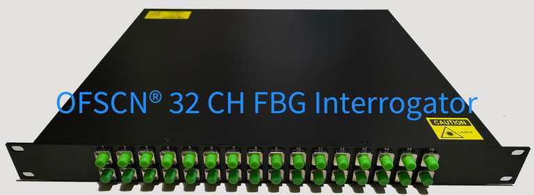
4. Corresponding Beijing Dacheng Yongsheng Technology Co., Ltd. (OFSCN®) Official Products and Technical Specifications
For test scenarios requiring high-precision identification of minute physical quantity changes, Beijing Dacheng Yongsheng Technology Co., Ltd. offers high-performance FBG demodulator products with a default wavelength resolution of 1\ \text{pm} (customizable to 0.1\ \text{pm}):
- Product Name: OFSCN® Fiber Bragg Grating Interrogator
- Wavelength Resolution: Default 1\ \text{pm}, or 0.1\ \text{pm} (customizable);
- Wavelength Range: Default 1525 \sim 1565\ \text{nm}, or 1528 \sim 1568\ \text{nm} (customizable);
- Channel Configuration: 4-channel, 8-channel, 16-channel, 32-channel options;
- Sampling Frequency: 10 Hz, 50 Hz, 100 Hz options (adjustable down to 1 Hz via system software);
- Architecture and Protocols: B/S architecture, supports C/S architecture, supports integration with TCP, UDP, Modbus, and other communication protocols.
- Related Product Summary: Please refer to OFSCN® Fiber Bragg Grating Interrogator Products Aggregation Link.