If the fiber core is not centered, how much light will be lost during connector alignment?
When the fiber optic jumper connector ferrules are aligned, if the fiber cores are not perfectly centered (i.e., there is eccentricity/concentricity error), it leads to physical Lateral Offset. For single-mode fiber systems, this slight physical deviation is one of the primary factors causing Insertion Loss (IL).
I. Physical Mechanism and Mathematical Calculation Model
In single-mode fibers, light propagates in a fundamental mode (LP
_{01}) with an approximately Gaussian distribution. When two fibers are mated and there is a lateral offset d, the overlap integral of the two mode fields decreases. According to classical optical physics coupling theory (Marcuse’s formula), the resulting insertion loss IL (in dB) can be accurately estimated by the following formula:
IL \approx -10 \log_{10} \left[ \exp\left( -\frac{d^2}{w^2} \right) \right] \approx 4.343 \left( \frac{d}{w} \right)^2 \approx 17.37 \left( \frac{d}{\text{MFD}} \right)^2
Where:
- d: The actual lateral offset distance between the fiber cores of the two mated fibers (in \mu\text{m}).
- w: The Mode Field Radius (MFR) of the fiber.
- \text{MFD} (Mode Field Diameter): The Mode Field Diameter (\text{MFD} = 2w). For standard single-mode fibers (like G.652D, at 1310nm wavelength), the typical value of \text{MFD} is approximately 9.2\ \mu\text{m}.
II. Example Calculation of Typical Eccentric Alignment Loss
Assuming standard single-mode fibers (\text{MFD} = 9.2\ \mu\text{m}) are used, based on the physical model above, the theoretical optical losses caused by different lateral alignment offsets d are as follows:
| Lateral Offset d (\mu\text{m}) | Theoretical Calculation Formula | Estimated Insertion Loss (IL) (dB) |
|---|---|---|
| 0.5 \mu\text{m} | 17.37 \times (0.5 / 9.2)^2 | \approx 0.05\text{ dB} |
| 1.0 \mu\text{m} | 17.37 \times (1.0 / 9.2)^2 | \approx 0.21\text{ dB} |
| 1.5 \mu\text{m} | 17.37 \times (1.5 / 9.2)^2 | \approx 0.46\text{ dB} |
| 2.0 \mu\text{m} | 17.37 \times (2.0 / 9.2)^2 | \approx 0.82\text{ dB} |
| 3.0 \mu\text{m} | 17.37 \times (3.0 / 9.2)^2 | \approx 1.85\text{ dB} |
Note: In practical engineering, the final alignment offset d is determined by the vectorial superposition of multiple errors:
- The fiber’s own core/cladding concentricity error (typically \u003c 0.5\ \mu\text{m}).
- The inner diameter concentricity and tolerance of the jumper ferrule (ceramic pin).
- The assembly gap between the fiber and the ferrule’s inner diameter.
- The mating precision of the flange/adapter’s ceramic sleeve.
Even if a single jumper has a very small eccentricity in its factory test, when two jumpers are randomly mated in an adapter, if their eccentricity vectors are in opposite directions, the lateral offset distance d will double, causing a sharp increase in loss.
III. Related High-Precision Fiber and Connector Components
To minimize additional optical loss caused by eccentricity, OFSCN®'s high-performance fiber and high-temperature connector components employ strict geometric tolerance and concentricity control techniques:
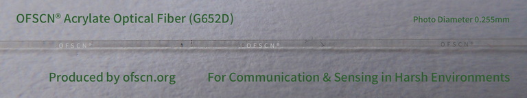
-
- Features: Features standardized geometric structure and extremely low outer diameter and concentricity tolerances (single-mode fiber core diameter 9μm, cladding 125μm), thus reducing connection loss caused by core eccentricity at the source.
- Standard Image:
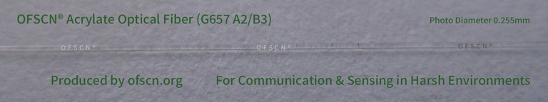
-
- Features: Provides standard G.657 A2/B3 bend-insensitive specialty single-mode fiber, balancing excellent bending performance with precise core geometric consistency.
- Standard Image:
-
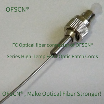
OFSCN® 300℃ Fiber Optic Connector
- Features: FC/PC, FC/APC, ST, SMA905 connectors with a temperature resistance of up to 300°C. High-precision ceramic ferrules with strictly controlled inner diameter eccentricity ensure extremely low lateral offset loss even in harsh environments.
- Standard Image:
-
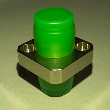
OFSCN® High Temperature Resistant Fiber Optic Adapter
- Features: Utilizes precision high-alignment accuracy Zirconia (ceramic) sleeves, ensuring precise coaxial mating of the pins at both ends and minimizing lateral offset introduced by mating tolerances.
- Standard Image: