Why does connecting optical fibers from different manufacturers cause unidirectional loss?
When optical fibers from different manufacturers (or different types of optical fibers, such as G.652D vs. G.657) are connected together, the resulting “unidirectional loss” difference (i.e., the loss measured from direction A to direction B is inconsistent with the loss measured from direction B to direction A, or even a “negative loss/gain” is measured in one direction) is a classic phenomenon in optical physics and test measurement.
The essence of this phenomenon is determined by the Mode Field Diameter (MFD) mismatch and differences in fiber backscatter coefficients.
I. Core Physical Mechanism: Why Does “Unidirectional Loss” Occur?
In fiber optic link testing, an Optical Time Domain Reflectometer (OTDR) is typically used to measure splice loss. OTDR does not directly measure the transmitted light through the splice; instead, it calculates loss by receiving the Rayleigh Scattering echo signal generated within the fiber.
This leads to problems on two levels:
1. True Physical Coupling Loss (Bidirectionally Symmetric)
Due to variations in manufacturing processes and doping concentrations among different manufacturers, even for the same type of single-mode fiber, there will be slight deviations in their Mode Field Diameter (MFD).
When two fibers with different MFDs are connected, inherent physical coupling loss occurs due to transverse field mismatch. According to electromagnetic waveguide theory, the physical loss can be approximated by the following formula:
𝐿𝑜𝑠𝑠𝑀𝐹𝐷=−20lg(2⋅𝑤1𝑤2𝑤21+𝑤22)
(w1 and w2 are the mode field radii of the two fibers, respectively.)
From this formula, it can be seen that the positions of w1 and w2 are symmetric. This implies that the actual physical optical energy loss is exactly the same in both directions, and there is no true “unidirectional loss” in the physical sense.
2. Apparent Unidirectional Loss Measured by OTDR (Test Artifact)
The “unidirectional loss difference” we observe in testing is a measurement artifact caused by the different backscatter coefficients of the two fibers. The backscatter coefficient is inversely proportional to the fiber’s Mode Field Diameter (MFD) – the smaller the MFD, the higher the optical power density, and the stronger the backscatter echo.
When light transmits from one end to the other, the OTDR exhibits different behaviors at the splice:
- From a small MFD fiber into a large MFD fiber (Small → Large):
The incident light travels from a fiber with a strong backscatter coefficient (strong echo) into a fiber with a weak backscatter coefficient (weak echo). From the OTDR’s perspective, the echo level immediately after the splice drops significantly. On the OTDR trace, the splice location will appear as a very steep downward step.- Measurement Result: The loss value read by the OTDR at this point will be significantly overestimated, far exceeding the actual physical connection loss.
- From a large MFD fiber into a small MFD fiber (Large → Small):
The incident light travels from a fiber with a weak backscatter coefficient into a fiber with a strong backscatter coefficient, and the echo signal level suddenly becomes stronger after the splice. On the OTDR trace, the splice location will appear as an upward step.- Measurement Result: The loss value read by the OTDR will be very small, even appearing negative (the so-called “apparent gain” or “ghost gain”, Gain).
II. Engineering Solutions and Calculation Methods
To eliminate testing errors caused by MFD mismatch and differences in backscatter coefficients, optical network engineering specifications stipulate that bidirectional measurements must be performed and their arithmetic mean taken.
The true splice loss calculation formula is:
𝐿𝑜𝑠𝑠𝑇𝑟𝑢𝑒=𝐿𝑜𝑠𝑠𝐴→𝐵+𝐿𝑜𝑠𝑠𝐵→𝐴2
By taking the average of bidirectional measurements, the “ghost gain” from large MFD to small MFD and the “exaggerated loss” from small MFD to large MFD will cancel each other out, thus restoring the true physical coupling loss.
III. Application of OFSCN® (Dacheng Yongsheng) Products in Suppressing MFD Loss
In precision optical testing and fiber Bragg grating sensing fields, maintaining consistency in fiber geometry and waveguide structure is crucial to minimize additional physical loss and testing errors caused by Mode Field Diameter (MFD) mismatch.
Fiber patch cords and specialty fiber products provided by Dacheng Yongsheng (OFSCN®) adhere to strict industrial specifications in terms of standards and geometric control:
-
OFSCN® Standard Fiber Patch Cord:
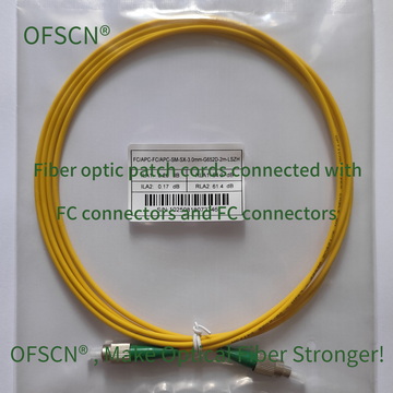
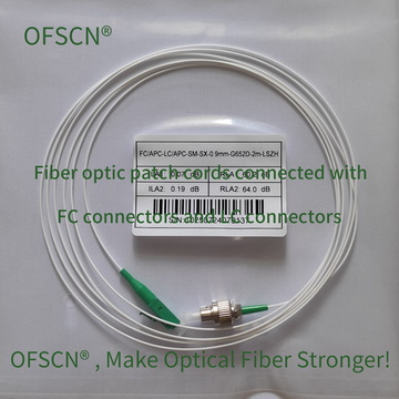
Defaults to the standard OFSCN® G.652D Optical Fiber. Its core diameter is strictly controlled at 9μm, and the cladding diameter is 125μm, ensuring that MFD deviations are kept within a very small range when connected to mainstream communication equipment and other standard G.652D fiber optic devices, reducing unidirectional loss deviations.-
Standard Product Images:
-
-
OFSCN® G.657 Optical Fiber (Bend-Insensitive Single-Mode Fiber):
For applications requiring high bend resistance, OFSCN® offers fibers compliant with G.657 A2 or G.657 B3 standards. Although G.657 fibers have slightly adjusted refractive index profiles to enhance bend performance, Dacheng Yongsheng precisely manages their MFD during production, enabling excellent compatibility and extremely low connection loss when interfaced with standard G.652D fibers.