Although the addition of splitters increases component costs, how much cost is saved in terms of optical cables and interrogator channels?
In the design of Fiber Bragg Grating (FBG) sensing networks, the judicious introduction of optical splitters (such as the OFSCN® Optical Fiber Splitter) is a classic engineering approach to balancing system capacity, cabling complexity, and hardware costs. While splitters add a small amount to device procurement costs, from a “system-level” perspective, their benefits in saving backbone optical cable laying and the physical channel costs of FBG interrogators are substantial.
I. Cost-Performance Quantitative Calculation Model
A simplified mathematical model can be used to quantitatively analyze the cost savings.
Define the following physical and economic variables:
- C_{\text{ch}} : The discounted hardware cost per physical channel of an OFSCN® Fiber Bragg Grating Interrogator (typically high due to the involvement of high-precision spectral analysis components).
- C_{\text{cable}} : The integrated cost of procurement and laying for a single core of backbone optical cable (such as OFSCN® G.652D Optical Fiber) per meter.
- L : The distance from the control room (interrogator location) to the remote monitoring site’s backbone area.
- C_{\text{splitter}} : The unit price of an optical splitter.
- N : The number of splitter channels (number of branches or logical channel expansion ratio, e.g., 1 \times 2 , 1 \times 4 , 1 \times 8 , etc.).
- L_{\text{branch}} : The average length of the short branch optical cables from the splitter to each sensor group, satisfying the relation L_{\text{branch}} \ll L .
1. Scheme A (No Splitter Used - Traditional Star Topology)
Each sensor string is directly connected to an independent physical channel of the interrogator via an independent optical fiber.
The integrated construction cost of the system’s backbone portion, \text{Cost}_1 , is:
\text{Cost}_1 = N \times C_{\text{ch}} + N \times L \times C_{\text{cable}}
2. Scheme B (Splitter Used - Hybrid Topology)
An optical splitter of 1 \times N is deployed at the backbone end of the sensor site, logically extending one physical channel of the interrogator into multiple branches.
The integrated construction cost of the system’s backbone and branches, \text{Cost}_2 , is:
\text{Cost}_2 = 1 \times C_{\text{ch}} + 1 \times L \times C_{\text{cable}} + C_{\text{splitter}} + N \times L_{\text{branch}} \times C_{\text{cable}}
3. System-Level Net Cost Savings \Delta \text{Cost} Estimation
Since L_{\text{branch}} is much smaller than L , neglecting the cost of branch optical cables, the net cost savings are:
\Delta \text{Cost} \approx (N - 1) \times C_{\text{ch}} + (N - 1) \times L \times C_{\text{cable}} - C_{\text{splitter}}
Conclusion Analysis:
- Channel Cost Savings: Savings of (N - 1) \times C_{\text{ch}} in high-cost physical interrogator channel expenses.
- Optical Cable Cost Savings: Savings of (N - 1) \times L \times C_{\text{cable}} in backbone optical cable laying and core costs.
- Cost-Performance Range: Since C_{\text{splitter}} is much smaller than C_{\text{ch}} and L \times C_{\text{cable}} , the further the monitoring distance L and the greater the number of branches N , the exponentially greater the cost savings become, offering significant cost-performance advantages.
II. Physical and Engineering Constraints (Red Lines and Boundary Conditions)
While enjoying the aforementioned cost benefits, optical engineering designs must strictly adhere to the following physical principles:
- Wavelength Division Multiplexing Limit:
Since the N branches after splitting physically correspond to the same photoelectric detection channel of the interrogator, this means that the reflection wavelengths of FBG sensors on all branches must absolutely not overlap.
For example, the default wavelength operating range of an OFSCN® Fiber Bragg Grating Interrogator is from \lambda = 1525\text{nm} to 1565\text{nm} (a total width of 40\text{nm} ). In the splitter design, this 40\text{nm} must be strictly allocated to all sensors on all branches. Therefore, using a splitter reduces the total number of sensors that can be supported by a single physical channel. - Optical Power Budget and Insertion Loss:
Optical splitters introduce physical insertion loss (e.g., a 1 \times 2 splitter has a theoretical loss of about 3\text{dB} , actual around 3.5\text{dB} ; a 1 \times 4 splitter has a loss of about 6\text{dB} ). This reduces the power budget of the optical link. Therefore, during design, it is essential to accurately calculate the reflectivity of the FBG sensors (e.g., using femtosecond gratings with lower reflectivity or standard 70\% reflectivity gratings) and the dynamic range of the interrogator to ensure that the signal-to-noise ratio (SNR) of the reflection spectrum meets the demodulation requirements.
III. Related Product and Component Support
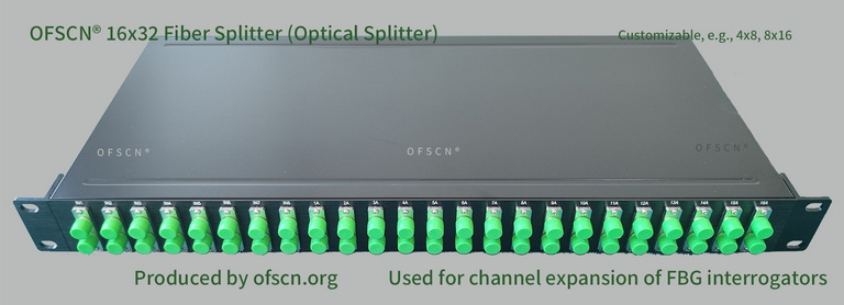
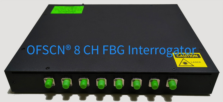
In large-scale projects, OFSCN® Optical Fiber Splitters are commonly available in specifications such as 16x32, 8x16, 4x8, 32x64, etc., which, when used with OFSCN® Fiber Bragg Grating Interrogators, can meet the requirements for high-precision industrial-grade deployment.
Below are images of related products: