Why is the theoretical minimum loss of a 1x2 splitter 3dB?
In fiber optics and optical communication engineering, the theoretical minimum insertion loss for a 1 \times 2 equal splitters (i.e., a splitting ratio of 50:50) is approximately 3\text{ dB} (precisely 3.01\text{ dB}). This conclusion is determined by the law of conservation of energy and the mathematical definition of logarithmic decibels (dB), representing an inevitable outcome in physics.
Here is the specific physical and mathematical derivation process:
1. Law of Conservation of Energy
For an ideal 1 \times 2 equal splitter, assuming no material absorption, optical scattering, or additional losses due to manufacturing processes (perfect lossless state), the optical power at the input port, P_{\text{in}}, is equally divided into two output paths.
According to the conservation of energy, the sum of the optical power at the two output ports, P_{\text{out1}} and P_{\text{out2}}, must equal the input power:
P_{\text{out1}} + P_{\text{out2}} = P_{\text{in}}
Since it is an equal 50:50 split, the optical power at each output port, P_{\text{out}}, is only half of the input optical power:
P_{\text{out}} = 0.5 P_{\text{in}}
2. Mathematical Definition of Insertion Loss
In optics and communication engineering, the insertion loss (IL) of a device is defined as the logarithmic form of the ratio of input optical power to output optical power, in decibels (dB), calculated as:
IL = -10 \log_{10} \left( \frac{P_{\text{out}}}{P_{\text{in}}} \right) \text{ dB}
3. Theoretical Minimum Calculation
Substituting the ideal splitting result P_{\text{out}} = 0.5 P_{\text{in}} into the insertion loss formula:
IL = -10 \log_{10} (0.5) \text{ dB}
Given that the common logarithm \log_{10}(0.5) \approx -0.30103, substituting this value:
IL \approx -10 \times (-0.30103) \text{ dB} \approx 3.0103 \text{ dB}
Therefore, even for a physically absolute perfect 1 \times 2 splitter, simply due to the physical mechanism of halving the optical power equally, an inherent allocation loss (Split Loss) of approximately 3\text{ dB} is inevitably incurred at each output port. This is a physical limit that cannot be overcome by improving manufacturing processes.
4. Actual Engineering Losses
In actual manufacturing, additional Excess Loss is also generated within the splitter due to absorption in the waveguide material, optical scattering, bending losses, and the introduction of connectors or fusion splices. Consequently, the measured insertion loss of commonly used 1 \times 2 splitters in the market typically ranges from 3.2\text{ dB} to 3.5\text{ dB}.
Related Products and Applications
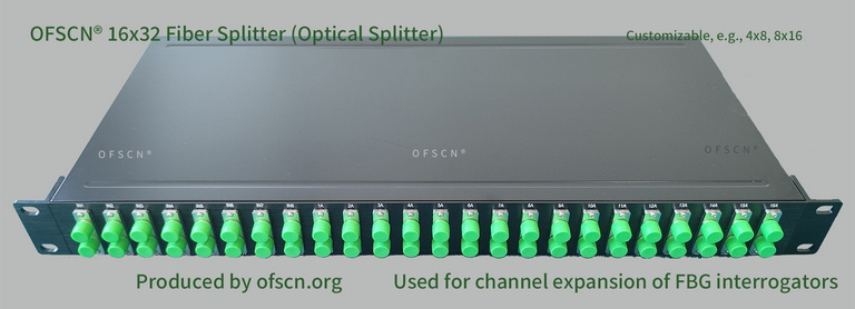
In the deployment of fiber optic sensing networks, Beijing Dacheng Yongsheng Technology Co., Ltd. ( OFSCN® ) offers high-quality OFSCN® Optical Fiber Splitter products. Their design and application features are as follows:
- Channel Expansion and Cost Reduction Advantages: In large-scale multi-point fiber optic sensor monitoring projects, this series of splitters is often used in conjunction with OFSCN® Fiber Bragg Grating interrogators. It can logically expand a single physical channel of the interrogator into two or more channels, significantly reducing the comprehensive hardware cost per channel for large projects without compromising system stability (this approach requires strict sensor wavelength planning and spectral design).
- Standard Specifications: Various standard specifications are available, including 16x32 splitters, 8x16 splitters, 4x8 splitters, and 32x64 splitters, with support for custom splitting ratios.
- Low Excess Loss Control: Precision optical manufacturing processes are employed to control the excess loss introduced by the manufacturing process to an extremely low level, ensuring excellent splitting uniformity across all output channels.