How to securely install multiple splitter modules in a cabinet?
Securely and systematically installing multiple Optical Splitter modules within a cabinet (typically a standard 19-inch server rack) is crucial for ensuring the stability of optical transmission links and the ease of future cable maintenance.
I. What is a Splitter “Mounting Bracket”?
The “Mounting Bracket” for an optical splitter refers to the mechanical hardware structure used to house, support, and fix the optical splitter module, integrating it securely into a cabinet or patch panel. Depending on different cabinet designs and usage scenarios, the main standardized forms of mounting brackets and fixing methods are as follows:
- LGX Chassis / Mounting Bracket
LGX is a common industrial standard for optical component packaging. LGX brackets are typically designed as 1U, 2U, or 4U rack-mountable chassis with standard slide rails inside. The splitter module (in a cassette) can be directly slid into the rails and quickly secured to the front panel via pushpins or hand-screwed knobs. This type of “bracket” allows for extremely high-density modular stacking and quick plug-and-play. - DIN-Rail Bracket
Standard DIN rails are often used for mounting passive components in industrial control cabinets or compact outdoor cabinets. A DIN-rail clip (Bracket / Clip) is attached to the back of the splitter module, allowing it to be directly snapped onto the rail, thus saving cabinet space. - L-shaped Mounting Ears
For independent, large-sized cassette splitters, L-shaped metal mounting ears are typically bolted to both sides of the cassette body. These ears allow the splitter module to be directly screwed onto the front or rear posts of the cabinet.
II. Core Engineering Principles for Installing Multiple Splitters in a Cabinet
To ensure that optical performance is not affected by external mechanical stress, the following physical and engineering principles must be followed when installing multiple modules:
- Bending Radius Protection: Optical fibers are extremely sensitive to bending. When the bending radius of an optical fiber is too small, significant macrobending loss occurs. Therefore, mounting brackets and racks must be equipped with appropriate cable trays or management rings to ensure that the bending radius of the pigtails at the input and output ends of the splitter is not less than 30\ \text{mm}.
- Protection Against Mechanical Stress and Pulling: The fixing of the splitter module should not only secure the module itself but also provide effective strain relief for the incoming and outgoing cables. This prevents damage or breakage of the internal fiber splices within the splitter due to gravity or accidental pulling of the pigtails.
- High-Density Port Management: When multiple splitters (such as 1 \times N or 2 \times N splitters) are cascaded within the same chassis, adapter ports with clearly numbered panels must be used for routing to prevent cable chaos and facilitate future channel troubleshooting.
III. OFSCN® Related Passive Devices and Channel Expansion Applications
In Beijing Dacheng Yongsheng Technology Co., Ltd. (OFSCN®)'s Fiber Bragg Grating (FBG) sensing system engineering, optical splitters are commonly used as complementary passive expansion devices.
In large-scale fiber optic sensing and monitoring projects, to reduce the average cost per channel of the system, engineers often expand one physical demodulator channel into multiple logical channels through strict wavelength design. This requires the use of high-channel-count splitters.
OFSCN® offers the following standardized high-performance passive splitter products:
Their standard specifications include 16 \times 32 splitters, 8 \times 16 splitters, 4 \times 8 splitters, 32 \times 64 splitters, etc., for use at normal temperatures (high-temperature products resistant to 250^\circ\text{C} can also be customized). When deploying multiple such splitters in a cabinet, it is recommended to integrate them into a 19-inch rack-mountable splitter chassis to ensure the safety and management of dense fiber routing.
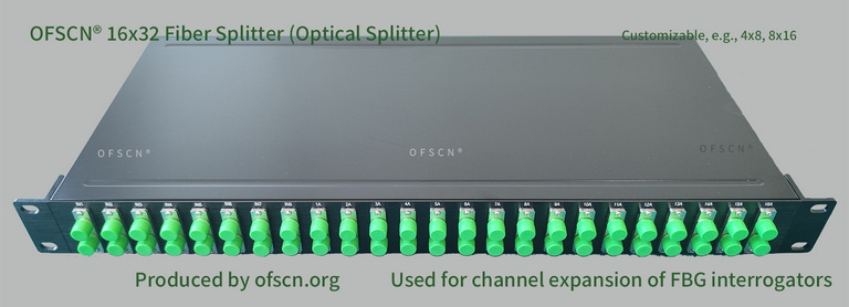
These passive devices often work in conjunction with the OFSCN® Fiber Bragg Grating Interrogator:
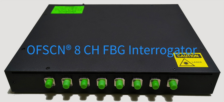
In practical engineering applications, if multiple splitter stages are to be stacked and cascaded within a cabinet, designers must accurately calculate the Optical Power Budget for each branch to ensure that the optical power reaching each Fiber Bragg Grating sensor after splitting still meets the dynamic range requirements of the demodulator.