In a vehicle-mounted or ship-mounted environment, does the splitting ratio of the splitter drift?
In complex environments such as vehicular or naval platforms, which are subject to high-frequency random vibrations, large impacts, and wide temperature cycles, the splitting ratio of optical fiber splitters may indeed experience transient or long-term drift.
The underlying physical mechanisms and engineering implications can be primarily attributed to the following three dimensions:
1. Physical Mechanisms and Environmental Stress Analysis
- Polarization State Fluctuations and Polarization-Dependent Loss (PDL): Under the jolting of a vehicle or high-frequency vibration from an engine, the transmission optical fiber undergoes minor physical bending and periodic stress-induced deformation. This introduces transient stress-induced birefringence within the fiber, leading to drastic and random fluctuations in the State of Polarization (SOP) of the transmitted light. If the splitter itself has significant Polarization-Dependent Loss (PDL), as the input polarization state changes with vibration, the loss in each output channel will fluctuate asymmetrically, macroscopically appearing as instantaneous fluctuations in the splitting ratio of each branch.
- Micro-Alignment Drift (Planar Lightwave Circuit - PLC Splitter): PLC splitters are typically manufactured by high-precision alignment of an input Fiber Array (FA), a PLC chip, and an output Fiber Array, followed by UV curing glue bonding and encapsulation. Under continuous mechanical vibration (e.g., vehicular 10\text{ Hz} \sim 2000\text{ Hz}) or intense instantaneous impacts, if the adhesive layer cannot fully isolate or absorb shear stress, it may undergo microscopic ( \mu\text{m}-level) mechanical creep or displacement. Since the direction and magnitude of alignment offset for each channel are difficult to be completely consistent, the Insertion Loss (IL) of each physical channel will change independently, consequently causing long-term or permanent imbalance in the splitting ratio.
- Evanescent Field Coupling Region Deformation (Fused Biconical Taper - FBT Splitter): FBT splitters achieve optical power coupling by stripping the coating of multiple fibers and then fusing and stretching them at high temperatures (the tapered region is usually extremely thin, only on the order of micrometers). In environments with strong vibration or impact, if the external sealing jacket and buffer gel have poor shock absorption capabilities, the geometric dimensions and refractive index distribution of the tapered region may undergo microscopic strain due to mechanical stress, directly altering the evanescent field coupling efficiency within the biconical taper and leading to splitting ratio drift.
2. Engineering Countermeasures for Improved Vibration Resistance Stability
To ensure long-term stability of the splitting ratio in harsh environments such as vehicular and naval platforms, splitters must comply with relevant engineering environmental standards (e.g., GR-1209-CORE or IEC 61300-2-1) and implement the following measures during manufacturing:
- Ultra-Low PDL Design: By precisely controlling the evanescent field distribution of the waveguide wavefront, ensure uniformity of the device under input polarization states, so that the splitting ratio remains constant even if polarization fluctuations occur due to vibration.
- High-Rigidity Damping Encapsulation: Employ stainless steel or alloy metal casings for overall encapsulation, filling the interior with special silicone or epoxy resins with excellent energy absorption and shock isolation properties to isolate external mechanical impacts.
3. OFSCN® Official Products and Applications
Beijing Dacheng Yongsheng Technology Co., Ltd. offers high-stability optical splitter products designed for deployment with high-precision sensing and optoelectronic test systems in complex environments:
Product Name: OFSCN® Optical Fiber Splitter | Official Link
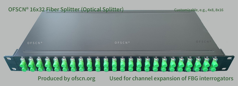
Key Parameter Specifications
- Product Category: Fiber Optic Splitter, Optical Splitter, Fiber Grating Splitter.
- Configuration: Standard configurations include 16\times32 splitters, 8\times16 splitters, 4\times8 splitters, 32\times64 splitters, etc., supporting normal temperature operation, with customization available for special products resistant to 250\ ^{\circ}\text{C} high temperatures.
- Application Scenarios: In large-scale monitoring projects (such as vehicular and naval sensing networks), this series of splitters is often used in conjunction with OFSCN® Fiber Grating Interrogators. By logically expanding the physical channels, the cost per channel monitoring is significantly reduced (Note: This application scenario requires strict wavelength allocation planning for each measurement point). Thanks to the highly reliable industrial-grade design, these splitters maintain excellent transmission loss and splitting stability in mechanical vibration environments, ensuring that the test system does not lose high-frequency sensor signals.