On an airplane or train, will the connectors experience signal flickering due to vibration?
In application scenarios involving broadband vibration and mechanical shock, such as aircraft and high-speed trains, whether fiber optic connectors generate “signal flicker” requires rigorous analysis from two perspectives: the physical characteristics of optical path connections and the sensing demodulation mechanism (intensity modulation vs. wavelength encoding):
I. Physical Mechanism: Why Fiber Connectors Experience Light Intensity Jitter in Vibrational Environments?
- Transient Micro-displacement of Ferrule End-faces
Fiber optic connectors (e.g., FC, SC, LC) rely on ceramic ferrules for alignment and slight pressure contact between end-faces. Under high-frequency vibration and alternating acceleration experienced by train bogies or aircraft skins, if the snap-fit or spring-loaded clamping mechanism undergoes axial or radial transient displacement on the micron scale, it leads to fluctuations in the alignment and coupling efficiency between the two fiber cores, resulting in transient jitter of Insertion Loss. - Fluctuations in Fresnel Reflection
If the connector end-face experiences sub-micron gaps due to vibration, the refractive index discontinuity at the air interface can cause transient interference and fluctuations in reflected light. In traditional systems based on light intensity transmission or detection, this phenomenon directly manifests as “flickering” of the received optical power.
II. Anti-Flicker Characteristics of FBG (Fiber Bragg Grating) Systems
In Fiber Bragg Grating (FBG) sensing systems, fluctuations in light intensity caused by vibration typically do not directly lead to signal distortion for the following physical reasons:
- Wavelength Encoding Principle
FBG sensors demodulate the central Bragg wavelength of the reflection spectrum, \lambda_B = 2 n_{\text{eff}} \Lambda (where n_{\text{eff}} is the effective refractive index and \Lambda is the grating period). - Light Intensity Attenuation Tolerance
As long as the optical power attenuation caused by mechanical vibration does not fall below the minimum dynamic detection sensitivity threshold of the demodulator (typically below -30\ \text{dBm} to -40\ \text{dBm} ), the demodulator can still lock onto the spectral peak center using algorithms like Gaussian fitting or centroid calculation. Therefore, purely slight fluctuations in light intensity do not affect wavelength detection accuracy and measurement stability. - Risk of Transient Drop-out
If a connector experiences instantaneous disconnection or attenuation exceeding the receiver’s dynamic range due to mechanical loosening or severe impact, the demodulator will result in instantaneous data point loss (Drop-out).
III. Engineering Countermeasures and Standards in Aircraft and Onboard Dynamic Testing
To completely eliminate the risk of signal interruption and flicker in environments with strong vibration, engineering practices typically adopt the following standards:
- Use Threaded Locking Connectors (FC Configuration)
Push-pull latching connectors (such as SC, LC) are strictly prohibited at measurement points with strong vibration. Threaded locking mechanisms, such as FC/APC, should be uniformly employed. The threaded coupling provides rigid locking, effectively resisting detachment caused by multi-axis vibration. - Employ APC (8° Angled Physical Contact) End-faces
The angled design of APC end-faces refracts reflected light into the cladding, achieving return loss better than 60\ \text{dB} . This completely avoids laser coherence jitter caused by reflected light returning to the source. - Fiber Fusion Splicing Recommended for Critical Measurement Points
In harsh conditions such as within the aircraft fuselage, on critical load-bearing structures of wings, or on train bogies, which are subject to extreme alternating stress over long periods, it is recommended to remove the patch cord connectors and perform permanent physical fusion using fiber optic fusion splicing to completely eliminate any mechanical alignment gaps. - Use Metal Armor Protection
Utilize fiber optic patch cords armored with metal capillaries to prevent the patch cord itself from generating micro-bending loss due to dangling or swinging.
IV. Related Product Specifications and Links
Beijing Dacheng Yongsheng Technology Co., Ltd. (OFSCN®) defaults to using threaded locking FC/APC connectors for environments with vibration, shock, and demanding dynamic testing conditions. They also offer armored patch cords and connector configurations with seamless all-metal sheathing:
- OFSCN® 120℃ Fiber Optic Connector
Features a metal threaded locking structure, available in FC/APC configuration, offering resistance to temperature and vibration, suitable for aerospace and onboard dynamic vibration monitoring.
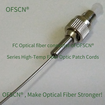
- OFSCN® 120℃ Fiber Optic Patch Cord
Encased in a 0.9mm seamless stainless steel alloy tube, containing a temperature-resistant polyacrylate fiber, and equipped with standard FC/APC threaded connectors, it possesses extremely high tensile strength, compressive strength, and resistance to mechanical jitter.



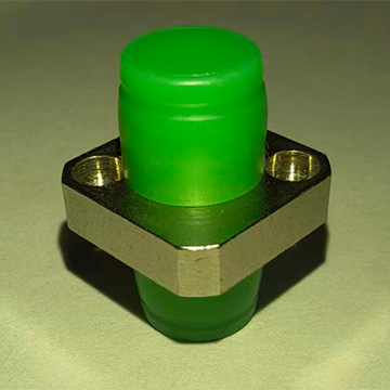
- OFSCN® High Temperature Resistant Fiber Optic Adapter
Features an all-metal housing and a precision ceramic alignment sleeve. When used with FC/APC-FC/APC interfaces, it ensures stable optical contact under a rigid bi-directional threaded connection.