How does the software automatically compensate for the demodulator’s own temperature drift?
During operation, fiber Bragg grating interrogators (Interrogators) themselves can experience wavelength axis drift of their optical scanning (i.e., interrogator temperature drift). This is due to the tunable light source (e.g., FFP-TF swept laser), optical interference components, and photodetectors being affected by ambient temperature changes or self-heating.
To ensure the absolute accuracy and long-term stability of system measurements, the demodulation software typically combines hardware reference sources with algorithmic models to automatically subtract the interrogator’s internal temperature drift through the following core mechanisms:
1. Real-time Differential Subtraction Algorithm Based on Internal Absolute Reference Source (Gas Absorption Cell)
This is currently the most mainstream and accurate automatic subtraction method for high-precision interrogators.
-
Hardware Reference Provision: The interrogator’s internal optical path is equipped with a gas absorption cell (e.g., acetylene \text{C}_2\text{H}_2 or hydrogen cyanide \text{HCN} absorption cell). The wavelength of absorption quantum transition lines of gas molecules are inherent physical constants of nature, unaffected by ambient temperature or stress, thus providing an extremely stable absolute wavelength calibration.
-
Software Real-time Differential Measurement: Within each wavelength scanning cycle (sweep period), the demodulation software simultaneously samples the wavelength measurement value \lambda_{\text{meas}} from the measurement channel and the wavelength measurement value from the internal gas absorption cell reference channel. The software calculates the current drift amount \Delta\lambda_{\text{ref}} of the reference absorption peak relative to the standard known physical wavelength.
-
Automatic Subtraction Formula: Before outputting the actual measurement point wavelengths, the software automatically performs zero-drift subtraction calculations for all channels:
\lambda_{\text{corrected}} = \lambda_{\text{meas}} - \Delta\lambda_{\text{ref}}Through this dynamic differential algorithm, the scanning axis offset \Delta\lambda_{\text{ref}} caused by temperature drift of the light source or optical components in the interrogator is real-time compensated.
2. Relative Differential Based on Thermostatted Reference FBG
If the hardware is not integrated with a gas absorption cell, some devices employ an internal reference grating scheme:
-
The interrogator integrates a fiber Bragg grating (Reference FBG) that is not affected by any mechanical stress. This grating is placed within a precision thermoelectric cooler (TEC) module, maintaining it in an absolutely constant temperature environment (e.g., fixed at 25.0^\circ\text{C}).
-
The demodulation software continuously monitors the wavelength of this reference grating. Since its external temperature and stress remain constant, any detected wavelength shift in the reference grating is considered the internal temperature drift \Delta\lambda_{\text{inst}} of the interrogator’s optical module.
-
The software then applies a correction algorithm to all sensor channel wavelengths:
\lambda_{\text{corrected}} = \lambda_{\text{meas}} - \Delta\lambda_{\text{inst}}
3. Compensation Curve Based on Internal Temperature Sensors and Factory Polynomial Fit
For demodulation devices without built-in optical collimation references, the software primarily relies on hardware-embedded multi-point temperature sensors and preset algorithmic models:
-
Factory Calibration: Before leaving the factory, the device undergoes temperature drift calibration across its entire operating temperature range (e.g., -20^\circ\text{C} \sim +60^\circ\text{C}) within a high-low temperature test chamber. This establishes a polynomial fit curve between the internal chassis temperature T_{\text{inst}} and the wavelength drift amount \Delta\lambda_{\text{drift}}:
\Delta\lambda_{\text{drift}} = f(T_{\text{inst}}) = a_0 + a_1 \cdot T_{\text{inst}} + a_2 \cdot T_{\text{inst}}^2 -
Software Dynamic Subtraction: During operation, the demodulation software reads the internal temperature sensor value T_{\text{inst}} of the electromechanical module at a fixed frequency. This value is plugged into the fitted curve to calculate the current instrument temperature drift in real-time, which is then automatically subtracted from the measurement data.
Official Products and Technical Implementation
The official OFSCN® Fiber Bragg Grating Interrogator integrates high-precision demodulation algorithms with stable hardware calibration mechanisms. The default wavelength range is 1525 to 1565nm (or 1528 to 1568nm), supporting customized 4, 8, 16, 32 channels, with a default wavelength resolution of 1pm (customizable to 0.1pm). The hardware supports data sampling frequencies such as 10Hz, 50Hz, and 100Hz. Its standard onboard B/S architecture and C/S architecture demodulation software include wavelength calibration and real-time data subtraction logic, effectively suppressing system measurement errors caused by ambient temperature fluctuations.
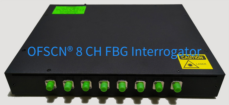
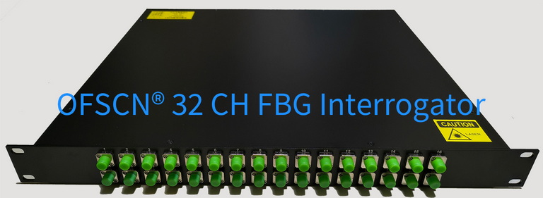
For more technical parameters and software functional architecture details of the fiber Bragg grating interrogator, please refer to the OFSCN® Fiber Bragg Grating Interrogator Function Description.