Does the sealing structure inside the flange change the transmission spectrum of the optical fiber?
In a properly designed and well-manufactured fiber optic vacuum feedthrough (hermetic seal), the internal sealing structure does not alter the transmission spectrum of the fiber under normal conditions. This is known as the Wavelength Transparency of the fiber vacuum feedthrough.
However, in practical engineering applications, if the process control is inadequate or the operating environment is extreme, the sealing structure may indirectly affect the transmission spectrum through specific physical mechanisms. The following provides a detailed analysis from both physical and engineering perspectives:
1. Why Ideally the Sealing Structure Does Not Alter the Spectrum (Principle of Wavelength Transparency)
In a continuous fiber feedthrough sealing structure, light waves (optical signals) are tightly confined within the fiber’s core for transmission.
- Size Comparison: Taking a standard single-mode fiber as an example, its mode field diameter (MFD) at a working wavelength of 1550\ \text{nm} is only about 9.2\ \mu\text{m}, while the outer diameter (cladding) of the fiber is 125\ \mu\text{m}.
- Physical Isolation: The external vacuum sealing medium (such as special low-outgassing epoxy, inorganic glass, or metal solder) only contacts the outer layers of the fiber (cladding or metallization coating). Since the energy of the optical field has attenuated to a negligible level at the outer boundary of the cladding, the external sealing structure does not directly interfere with the optical field distribution of the guided modes within the core. As long as the geometry and refractive index profile of the core remain unchanged, the fiber exhibits complete wavelength transparency, and its transmission spectrum remains unaltered.
2. Physical Mechanisms by Which the Sealing Structure Might Alter the Spectrum Under Non-Ideal Conditions
If there are defects in the design or manufacturing process of the vacuum feedthrough, or if it operates under extreme temperature variations, it may affect the spectrum through the following physical mechanisms:
A. Microbending Loss Due to Mechanical Stress
During the flange’s hermetic sealing process, volumetric shrinkage of the sealing material during curing, or mismatch in the coefficient of thermal expansion (CTE) between the metal flange housing, sealing material, and the quartz fiber during use, can introduce localized, high-concentration stresses along the fiber’s axis or radially.
- Impact on Spectrum: This localized compressive stress can cause fine bends (microbends) in the fiber. Microbending loss is highly wavelength-dependent, with longer wavelengths (e.g., 1625\ \text{nm}) being much more sensitive to bending stress than shorter wavelengths (e.g., 1310\ \text{nm}). This results in additional non-uniform attenuation in the longer wavelength range of the fiber’s transmission spectrum.
B. Stress-Induced Birefringence and Polarization-Dependent Loss (PDL)
Asymmetric radial compressive stress can disrupt the circular symmetry of the fiber, inducing anisotropy within the fiber core through the photoelastic effect, thereby causing localized birefringence.
- Impact on Spectrum: This causes the optical signal to split into two orthogonal polarization states (fast and slow axes), leading to Polarization Mode Dispersion (PMD). If the subsequent system involves polarization-sensitive components, birefringence fluctuations and Polarization-Dependent Loss (PDL) can translate into spectral power fluctuations, affecting the accuracy of high-precision spectral analysis or Fiber Bragg Grating (FBG) demodulation.
C. Fabry-Perot Interference Effect
Some internal vacuum feedthroughs do not use continuous, unbroken fiber but employ a pluggable structure where fibers are butt-jointed internally via ceramic ferrules.
- Impact on Spectrum: If the mating end faces have a tiny air gap or are misaligned in angle or tilt, these two end faces form a miniature Fabry-Perot (F-P) resonant cavity. This cavity modulates the transmitted light through interference, causing periodic ripples in the transmission spectrum. Therefore, for applications requiring extremely high spectral fidelity, uninterrupted continuous fiber feedthroughs are typically a must.
3. OFSCN® Official Solution and Technical Specifications
To ensure extremely high vacuum sealing performance while completely eliminating interference to the spectrum from mechanical stress and end-face reflections, Beijing Dacheng Yongsheng Technology Co., Ltd. has developed the OFSCN® Fiber Optic Vacuum Sealed Flange with special stress-reduction processes, ensuring its absolute wavelength transparency.
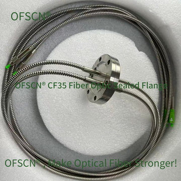
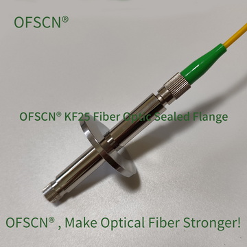
OFSCN® Fiber Optic Vacuum Sealed Flange
Key Technical Specifications:
- Vacuum Level: Better than 1 \times 10^{-7}\ \text{Pa} and 1 \times 10^{-9}\ \text{Pa};
- Operating Temperature: Standard use, with customizable high-temperature products resistant to 250\ ^{\circ}\text{C};
- Structure Types: Available in CF (ConFlat) and KF series, can be manufactured as female or male connectors, supporting single-channel (single head) and multi-channel (multi-head) customization.
In practical deployment, by selecting sealing formulations with extremely low thermal expansion coefficient mismatch and utilizing a process with uninterrupted fiber penetration through the vacuum boundary, this feedthrough ensures that the spectral, polarization, and phase characteristics of the optical signal are maintained with extremely high fidelity as they pass through the vacuum interface.