Will forcing a ferrule and a flat end face together damage the fiber optic cable?
Yes, forcibly inserting an angled physical contact (APC) and a planar physical contact (PC/UPC) fiber optic connector together can easily damage the fiber end face (physical damage) and severely degrade optical path transmission performance.
In fiber optics communication and optical engineering, such an operation is considered a serious violation of specifications. The following provides a detailed academic analysis from three perspectives: physical mechanics, damage mechanisms, and optical performance:
I. Physical Mechanics Analysis: Geometric Mismatch and Ultra-High Pressure
- Structural Differences:
- PC/UPC (Physical Contact) Connectors (usually blue): The end face of the ferrule is a microsphere perpendicular to the fiber axis (commonly referred to as flat).
- APC (Angled Physical Contact) Connectors (usually green): The end face of the ferrule is a micro-spherical surface angled at 8^\circ.
- Stress Concentration Effect:
- When fiber connectors are mated within an adapter, they rely on an internal spring mechanism to provide a continuous axial pressing force F (typically around 10\ \text{N} for standard connectors) to achieve “Physical Contact” of the fiber core.
- When an angled end face is forcibly mated with a flat end face, due to the inability to conform geometrically, the original uniform “face contact” degenerates into an extremely small point contact. That is, the very tip of the APC’s angled surface directly presses against the UPC’s flat surface.
- According to the pressure formula:P = \frac{F}{A}Since the contact area A shrinks drastically towards zero, under the same pressing force F, the local instantaneous pressure P at the contact point increases exponentially, far exceeding the yield strength and fracture limit of silica (glass fiber) and zirconia (ceramic ferrule).
II. Physical Damage Mechanisms
This extreme localized stress concentration can lead to the following permanent damages:
- Fiber Core Chipping & Cracking: The highly hard and brittle silica glass fiber core is prone to micro-cracks or direct chipping under localized immense pressure, resulting in permanent damage to the fiber end face.
- Severe End Face Scratches: During insertion and rotational locking, the two end faces undergo hard friction under ultra-high pressure, causing deep grooves in the critical core area.
- Plastic Deformation of Ceramic Ferrule: The tip of the zirconia ceramic material may also undergo slight physical wear or deformation, preventing the patch cord from achieving perfect physical contact even when reconnected to a compatible connector later.
III. Optical Performance Degradation
Even if the fiber miraculously avoids visible cracks during a single forceful insertion, its optical performance will suffer catastrophic attenuation:
- Extremely High Insertion Loss (IL): Due to the wedge-shaped air gap (Air Gap) between the angled and flat surfaces, the fiber cores cannot be properly aligned, causing severe scattering and divergence of the light signal during transmission. Insertion loss typically spikes to 3\ \text{dB} to over 10\ \text{dB} (normal mating should be less than 0.3\ \text{dB}), severely obstructing the optical path.
- Very Low Return Loss / Intense Reflection (RL): The difference in refractive index between air (approx. 1.0) and silica glass (approx. 1.45) causes strong Fresnel Reflection at the wedge-shaped air gap. This causes the return loss, which should normally be above 50\ \text{dB} (UPC) or 60\ \text{dB} (APC), to degrade drastically to around 10\ \text{dB} to 20\ \text{dB}. Intense reflected light returning to the light source can cause laser instability, increased noise floor, or signal saturation in fiber Bragg grating demodulators.
IV. Industry Standards and Fail-Safe Design
To completely prevent such physical and optical damage, the fiber optics industry employs color coding for fail-safe management:
- Blue Ferrules/Connectors: Indicate PC/UPC (perpendicular/flat) standard.
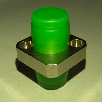
- Green Ferrules/Connectors: Indicate APC (8^\circ angled) standard.
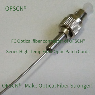
In OFSCN®'s high-temperature, high-reliability fiber optic sensing systems, all adapters, connectors, and patch cords strictly adhere to and provide this standard. For example, when deploying an APC system, dedicated APC high-temperature adapters and connectors must be used:
OFSCN® High Temperature Resistant Fiber Optic Adapter | Official Link
OFSCN® 300℃ Fiber Optic Connector | Official Link
In practical engineering operations, mixing and inserting across colors and end-face types is strictly prohibited. If a transition between APC and UPC equipment is necessary, a dedicated conversion patch cord with one end as APC and the other as UPC (e.g., a custom OFSCN® Standard Fiber Patch Cord) should be used, rather than forcibly mating them in an adapter.