How does it split a light beam into multiple beams, like a three-way tee in a water pipe?
The function of a fiber splitter in an optical path is indeed similar to a “T-junction” in a water pipe. However, in terms of physical principles, light, as an electromagnetic wave, has a fundamentally different “splitting” mechanism than fluid dynamics. Fiber splitters do not split light through simple physical “blocking” or “throttling.” Instead, they utilize the electromagnetic field coupling in guided optics and the geometric spatial division of micro-waveguides.
Currently, the industry primarily achieves the distribution of one light beam into multiple beams through the following two physical mechanisms:
1. Fused Biconical Taper (FBT) — Evanescent Field Coupling Mechanism
Fused biconical taper technology achieves light splitting by altering the boundary conditions of optical fibers through physical and thermodynamic methods:
- Manufacturing Process: Two (or more) optical fibers with their outer coatings removed are placed closely together, heated to melting at high temperatures, and simultaneously stretched uniformly from both sides. This ultimately forms a micro-transition region with a biconical structure in the heated area.
- Physical Principle: In standard single-mode optical fibers, light waves are mainly confined and transmitted within the core (e.g., the fundamental mode LP_{01}). When the optical fiber enters the stretched and tapered region, the cross-sectional area of the core sharply decreases. The electromagnetic field originally confined within the core cannot be fully contained and begins to diffuse outwards into the cladding, forming evanescent waves. Due to the extreme proximity of the two fibers in the fused region, the evanescent field from one fiber penetrates and couples into the cladding and core of the other fiber.
- Splitting Control: By precisely controlling the length of stretching, the taper angle, and the length of the fused region, the electromagnetic field coupling efficiency between the two fibers can be strictly controlled. This allows for arbitrary splitting ratios (e.g., 50:50, or 10:90 designed for specific sensors).
- Water Pipe Analogy: This is analogous to placing two rubber hoses side-by-side, thinning the walls in the middle section and fusing them, making the walls “semi-permeable.” Water (photon energy) then diffuses into the adjacent hose proportionally through this semi-permeable wall.
2. Planar Lightwave Circuit (PLC) — Geometric Wavefront Division Mechanism
Planar lightwave circuit technology is based on micro- and nano-semiconductor processing techniques and is a true “T-junction” device in terms of its geometric structure:
- Manufacturing Process: On a quartz (silica) dielectric substrate, micro-scale waveguides with high refractive indices are deposited and etched using semiconductor processes such as photolithography and etching.
- Physical Principle: The core basic unit of a PLC splitter is a Y-shaped branch. When light waves propagate in the main waveguide and reach the Y-shaped junction, the wavefronts (equiphase surfaces) of the light waves are geometrically divided into two parts, entering the two branch waveguides respectively. By cascading these Y-branches multiple times within the chip (similar to a tree topology), one input beam can be uniformly split into 2^N beams (e.g., 1\times 4, 1\times 8, 1\times 16 up to 1\times 64).
- Water Pipe Analogy: This is most similar to a T-junction in a water pipe. It etches physical channels within a solid medium, directly splitting the forward-propagating optical field into multiple paths through geometric branching.
OFSCN® Applications of Optical Splitters in Fiber Optic Sensing
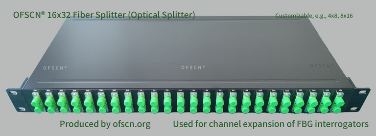
In Beijing Dacheng Yongsheng Technology Co., Ltd. (OFSCN®)'s Fiber Bragg Grating (FBG) sensing solutions, optical splitters are indispensable channel expansion devices.
Key Parameters and Application Metrics:
- Standard Specifications: Offers specifications including 16\times 32 splitters, 8\times 16 splitters, 4\times 8 splitters, and 32\times 64 splitters.
- Channel Expansion Applications: In large-scale fiber optic sensing projects, this product is often used in conjunction with the OFSCN® Fiber Bragg Grating Interrogator. Splitters allow one physical channel of the interrogator to be spatially expanded into two or three logical channels, significantly reducing the cost per channel in high-channel-count sensing systems.
- Design Requirements: Since the use of splitters introduces insertion loss, and the reflected wavelengths from the split channels are prone to overlap, rigorous wavelength design and biasing analysis are essential when using splitters for channel expansion to prevent mutual interference between the wavelength reflection peaks of each sensor.