After troubleshooting equipment failures, where are patch cords most likely to cause problems?
After ruling out active equipment failures such as fiber optic demodulators, light sources, or detectors, common failure points for fiber optic patch cords causing sudden optical signal attenuation or complete interruption are primarily concentrated in the following locations, based on engineering statistics and physical failure probability:
1. Ceramic Ferrule End-Face (Core Optical Path Alignment Area)
Fiber optic connectors’ end-faces (e.g., FC/APC, FC/PC, LC, SC, etc.) are precision optical interfaces for light signal transmission. The mode field diameter of single-mode fiber is only about 9 \ \mu\text{m} to 10.4\ \mu\text{m}. The most common failure modes at this location include:
- Dust and Grease Contamination: Airborne particulate matter, contamination from operators’ fingers, debris remaining inside protective caps, or particles generated from wear within the ferrule can adhere to the fiber core surface. This obstructs the optical path or causes strong scattering, leading to degraded return loss or even complete optical path interruption.
- Physical End-Face Scratches and Chipping: Direct mechanical mating and fastening in the presence of hard particles can easily cause irreversible pits or scratches on the polished end-face, especially in the fiber core area.
- Incomplete Physical Contact of End-Faces: Loosely tightened connector threads, improperly seated retaining clips, or a shattered ceramic split sleeve within the adapter (ferrule) can create an air gap between the mating end-faces, resulting in severe insertion loss.
2. Connector Strain Relief Boot Root
The junction between the connector’s metal/plastic housing and the rear strain relief boot is a critical stress concentration point for the patch cord:
- Local Excessive Bending Leading to Fiber Breakage: When the patch cord is subjected to violent lateral pulling, sustained gravity, or sharp right-angle bends, if the strain relief mechanism at the boot cannot fully buffer the bending deformation, the internal quartz glass fiber (cladding diameter 125\ \mu\text{m}) is highly susceptible to micro-crack propagation or instantaneous stress fracture at this junction.
- Sheath and Connector Detachment: Excessive tensile force can cause the crimp ring to fail, leading to the internal fiber directly bearing axial tensile load and breaking.
3. Mechanical External Force Damage to the Patch Cord Body (Crushing and Small Bend Radius)
Standard fiber optic patch cords (e.g., with PVC jackets) have limited mechanical compression and tensile strength:
- Crushing by Cabinet Doors and Heavy Objects: The patch cord can be flattened by metal edges at cable trays or cabinet exits, or crushed by equipment carts or stepped on by personnel. Due to the limited resilience of PVC jackets, instantaneous localized impact forces can directly shatter the internal quartz fiber core.
- Macro-bend Loss / Fatigue Fracture Induced by Small Bend Radius: The long-term safe bend radius for standard G.652D fiber is typically recommended to be greater than 30\text{ mm}. When a patch cord is tied in a knot or wound too tightly, total internal reflection can fail at the bend (light radiates outside the cladding), causing sharp signal attenuation. Prolonged exposure to extremely small bend radii can also accelerate the propagation of microscopic glass cracks, ultimately leading to breakage.
Comparison of Structural Protection and Related Industrial Patch Cord Solutions
Conventional laboratory-grade patch cords (e.g., OFSCN® Standard Fiber Patch Cord) use PVC jackets combined with aramid (Kevlar) for tensile protection, suitable for static cabling within data center racks.
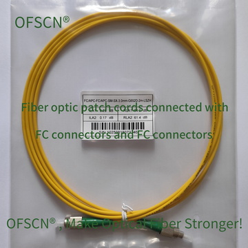
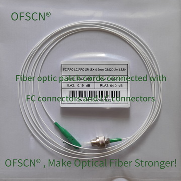
For industrial monitoring, in-vehicle testing, or long-term harsh outdoor environments, to prevent breakage at the boot root and damage from crushing, metal armoring or steel wire rope reinforced structures are typically employed for comprehensive physical protection:
- Micro Steel Armored Patch Cord: For example, OFSCN® 2.0mm Micro Steel Armored Fiber Optic Patch Cord, which embeds a 0.6\text{ mm} seamless stainless steel tube within the PVC jacket. This effectively resists side pressure, shear forces, and limits the minimum bend radius, preventing the fiber core from being crushed.
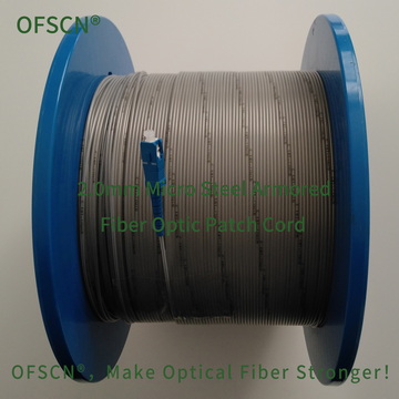
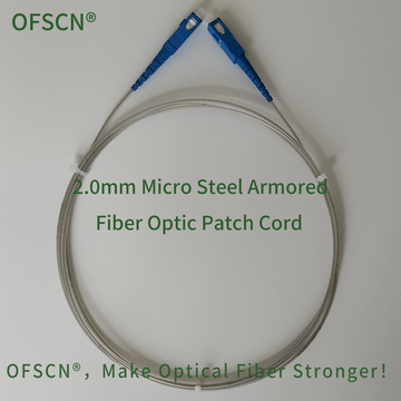

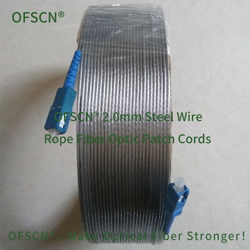
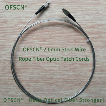
- Steel Wire Rope Patch Cord: For instance, OFSCN® 2.0mm Steel Wire Rope Fiber Optic Patch Cord and OFSCN® 3.0mm Steel Wire Rope Fiber Optic Patch Cord, which use galvanized/stainless steel wire twisted structures to encase a stainless steel capillary steel tube. The tensile strength can reach over 1200\text{ N} to 1500\text{ N}, and the compressive strength is > 150\text{ MPa}, preventing breakage at the root and damage from being stepped on or run over.

Quick Troubleshooting Steps Recommendation
- End-Face Cleaning and Microscopic Inspection: Use a professional fiber optic end-face cleaning pen/lint-free wipe to clean the ferrules at both ends of the patch cord, and use a fiber end-face inspection scope to observe the fiber core area for permanent scratches or burns.
- Visual Fault Location (VFL) with Red Light Pen: Inject red light and observe along the connector boot and the entire patch cord body for any conspicuous red light leakage (the point of red light leakage indicates internal fiber breakage or severe micro-bend failure).
- Adapter Replacement Test: Rule out issues of optical axis misalignment caused by a shattered ceramic sleeve within the adapter (ferrule).