During conduit installation, how can joints be protected from being pulled apart and from dust ingress?
During the conduit installation of fiber optic cables (including various Fiber Bragg Grating sensors, fiber optic patch cords), fiber optic connectors (such as FC, SC, LC, etc.) and the transition zone (Boot) between the connector and the optical cable are the most vulnerable weak points. If the connector is pulled directly without protective measures, it can easily lead to fiber breakage, connector detachment, or ferrule damage, while also introducing micro-dust contamination.
To achieve the goal of “no pulling damage, no dust ingress,” the following core physical and engineering protection principles must be followed:
I. Core Protection Principles
-
Tension Bypass Transfer
Mechanically, the tensile force F must never be directly applied to the connector body, ceramic ferrule, or the exposed portion at the fiber root. A physical clamping mechanism must be used to bypass the connector and transfer the tensile force directly onto the strength members of the cable jacket (such as aramid yarn, stainless steel seamless tube, or outer stranded steel wires), ensuring the connector remains in a completely zero-stress state during pulling. -
Micron-Level Sealing
Conduit interiors typically contain construction debris, dust, or water. High-sealing, flexible sleeves or sealed chambers must be used to completely enclose the connector end face. The protection level must be sufficient to prevent the ingress of particles with a diameter \ge 0.1\ \mu\text{m} , preventing degradation of insertion loss and return loss due to friction or dust contamination of the optical end face during conduit pulling.
II. Protective Techniques for Conduit Installation
In actual engineering construction, the following specific methods are commonly employed:
1. Using Dedicated “Pulling Grip Sleeves” and “Protective Conduits” (Cable Pulling Grip with Protective Tube)
This is a standard configuration for industrial-grade construction:
- Structural Design: Consists of a metal pull ring at the front, a stainless steel mesh sleeve (or a special high-strength plastic sleeve) in the middle section, and a rope fitting at the rear.
- Working Mechanism: The fiber optic connector (with dust cap attached) is placed inside a rigid protective tube within the mesh sleeve, with the rear end tightly clamped onto the optical cable jacket. When the front pull ring is pulled, the mesh sleeve tightens, and the tensile force is applied directly to the outer jacket and strength members of the optical cable, leaving the connector suspended and protected inside the conduit.
2. DIY Heat Shrink Tubing and Tape Sealing Protection (On-site Temporary Solution)
If commercial pulling grips are unavailable, a DIY protective structure can be used on-site:
- Step 1: Ensure the connector dust cap is securely attached and wrap the connector head with residue-free electrical tape.
- Step 2: Slide a relatively long piece (typically 15\ \text{cm} to 30\ \text{cm} ) of heat shrink tubing (preferably double-walled heat shrink tubing with inner hot-melt adhesive) over the connector, such that the front end extends about 5\ \text{cm} beyond the connector and the rear end extends onto the optical cable jacket.
- Step 3: Heat shrink it evenly with a heat gun to tightly seal the connector and the optical cable. Flatten and punch a hole in the extended front portion of the heat shrink tubing while it’s hot to serve as the pulling attachment point. This way, the pulling force is directly transmitted to the optical cable through the heat shrink tubing’s outer shell.
- Step 4: Wrap the exterior with PTFE lubricating tape to reduce friction resistance during conduit pulling.
III. Related Information on Beijing Dacheng Yongsheng Technology Co., Ltd. (OFSCN®) Products
Please note that “conduit pulling grip sleeves” or “conduit connector protection sleeves” are general auxiliary tools for engineering construction and are not part of Beijing Dacheng Yongsheng Technology Co., Ltd.'s (OFSCN®) core product line.
However, Beijing Dacheng Yongsheng (OFSCN®) considers the root bend-prevention and pull-resistance characteristics of connectors in the design of its related passive components and Fiber Bragg Grating (FBG) sensors:
- Transition Section Reinforced Sleeve: In the single-point or multi-point Fiber Bragg Grating (FBG) sensors/patch cords produced by Beijing Dacheng Yongsheng, the connector tail end typically includes an approximately 10\ \text{cm} bend relief sleeve to prevent stress concentration at the root during routine cabling.
- High Tensile Strength Armored Patch Cords: If the installation environment involves extremely high pulling forces and limited space, making it inconvenient to use complex grip sleeves, it is recommended to opt for special steel wire stranded armored fiber optic patch cords, which possess inherently strong tensile and compressive resistance, to withstand external pulling forces through their own armor:
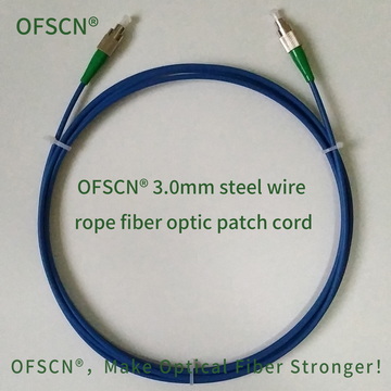
1. OFSCN® 3.0mm Steel Wire Rope Fiber Optic Patch Cord
This product adds a high-density 0.45\ \text{mm} stainless steel wire stranded structure and a polyethylene (PE) outer jacket over the stainless steel seamless tube. It offers excellent tensile and compressive mechanical properties, with a tensile strength of T ext{ > } 1200\ \text{N} , capable of directly and effectively resisting strong pulling forces during conduit installation.
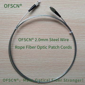
2. OFSCN® 2.0mm Steel Wire Rope Fiber Optic Patch Cord
Utilizes an all-metal structure, composed of a 0.6\ \text{mm} galvanized steel wire stranded layer and a 1.0\ \text{mm} stainless steel seamless steel tube. It is specifically designed for harsh industrial and high-tensile installation scenarios, exhibiting extremely strong tensile and bend-resistant capabilities.