On the patch panel, how can the channel assignment of sensors be flexibly adjusted using patch cords?
In fiber sensing and communication engineering, “Cross-Connect” is a classic and efficient physical layer topology. Compared to “Interconnect,” cross-connect introduces a Double-Panel design between the demodulation equipment and field sensors, greatly enhancing channel allocation flexibility and system maintainability.
The following details how to flexibly adjust sensor channel allocation on patch panels using patch cords from three perspectives: physical topology, operating principles, and engineering practices.
I. Physical Topology Structure of “Cross-Connect”
In a typical Fiber Bragg Grating (FBG) sensor monitoring system, the cross-connect architecture includes the following three core physical partitions:
- Active Equipment Patch Panel:
- The back of this patch panel is directly connected to the physical channels (e.g., Ch1, Ch2, …, ChN) of the FBG demodulator (or other optical transmission/reception equipment).
- The adapter (flange) interfaces on the front of the patch panel correspond one-to-one with the demodulator channels.
- Field/Outside Plant Patch Panel:
- The back of this patch panel connects to the installed multi-core backbone optical cables, which lead to the FBG sensor strings in various areas.
- The adapter interfaces on the front of the patch panel correspond one-to-one with the physical links of the sensors (or sensor groups) in the field.
- Patch Cords:
- Located between the two patch panels mentioned above. High-quality fiber optic patch cords are used to connect any channel flange on the “Equipment Side” to any sensor flange on the “Field Side.”
II. How to Flexibly Adjust Channel Allocation via Patch Cords?
When sensor channels need to be reallocated, expanded, or isolated due to faults, there is no need to use a splicing machine or change the backbone cable layout. Simply operate the patch cords on the front of the patch panel:
1. Channel Reconfiguration and Load Balancing (Wavelength Resource Optimization)
- Background: FBG sensors operate based on Wavelength Division Multiplexing (WDM) technology. If the number of sensors on a backbone channel increases, causing reflection wavelength overlap, or if high-frequency sampling sensors need to be moved to high-speed channels of the demodulator.
- Operation: Unplug the patch cord of the sensor link at the “Equipment Side Patch Panel” and insert it into another demodulator channel flange with idle wavelength bandwidth or higher sampling rate.
2. Quick Bypass of Physical Channel Faults
- Background: When a physical channel optical module of the FBG demodulator fails or degrades, the sensors under that channel cannot be read.
- Operation: No need to disassemble the equipment. Simply unplug the patch cord corresponding to the faulty channel from the old port on the equipment side patch panel and reallocate it to a reserved spare equipment channel flange. Monitoring can be restored within seconds.
3. Logical Channel Expansion (with Optical Splitters)
- Background: In large monitoring projects, to reduce the cost per channel, it is common to expand one physical channel into multiple logical channels (provided that the wavelengths of the FBG sensors on each branch do not overlap).
- Operation: Connect an optical splitter in series between the equipment side and field side patch panels. Use patch cords to connect one port of the demodulator to the splitter input, and then use multiple patch cords to connect the splitter outputs to different sensor links on the field side patch panel.
III. Engineering-Grade Key Component Recommendations
In the cross-connect architecture, repeated plugging and unplugging of patch cords and the contact performance of patch panel flanges have a decisive impact on the overall optical loss (attenuation and reflection noise) of the system. To ensure high-precision, high-signal-to-noise ratio FBG demodulation, the following industrial-grade or special-grade components are typically recommended:
1. Basic Patch Cords
In the room temperature environment of the machine room and distribution boxes, standard single-mode precision patch cords can be used:
-
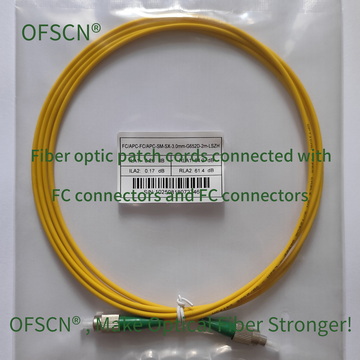
OFSCN® Standard Fiber Patch Cord: Default configuration with high return loss FC/APC connectors (greatly reducing reflection noise affecting FBG demodulation), default diameter of 3.0mm, using G.652D fiber, and length can be customized.
(OFSCN® Standard Fiber Patch Cord - FC/FC Diagram)
2. Harsh Environment/High Mechanical Strength Patch Cords
If the patch panel is deployed in an industrial field, vehicle-mounted, or other complex environments with tensile stress and bending stress, metal armored patch cords are recommended:
-
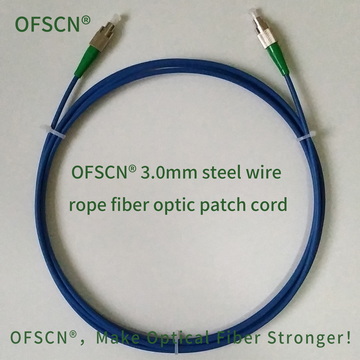
OFSCN® 3.0mm Steel Wire Rope Fiber Optic Patch Cord: Integrates a 0.9mm stainless steel seamless steel tube and a 0.45mm stainless steel wire twisted structure inside. It has a tensile strength greater than 1200N and a compressive strength greater than 200MPa, effectively preventing physical damage from on-site construction or frequent patching.
(OFSCN® 3.0mm Steel Wire Rope Armored Fiber Optic Patch Cord)
3. Patch Panel Flanges (Adapters)
The plug-unplug lifespan and alignment accuracy of the flange determine the long-term stability of the cross-connect:
-
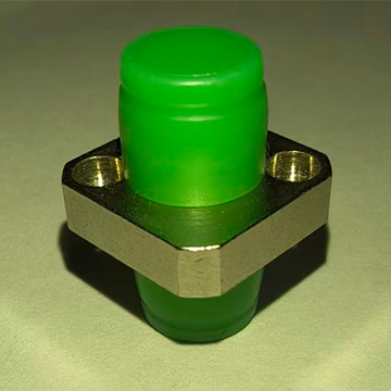
OFSCN® High Temperature Resistant Fiber Optic Adapter: Provides a high-precision zirconia ceramic alignment sleeve to ensure ultra-low insertion loss (Insertion Loss) during repeated plugging and unplugging, and supports a temperature resistance limit of up to 300℃.
(OFSCN® High Temperature/High Precision Fiber Optic Adapter)
4. Channel Expansion Splitters
-
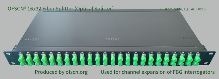
OFSCN® Optical Fiber Splitter: Offers various splitting specifications from 1x2, 1x4, 1x8 to 16x32, used at the patch panel to logically expand a single demodulator physical channel to multiple sensor links.
(OFSCN® Optical Fiber Splitter)
Through the “Cross-Connect” design of double patch panels, combined with high return loss precision patch cords and adapters like FC/APC, the maintenance, channel allocation, and system upgrades of fiber optic sensor systems become extremely efficient, intuitive, and safe.