In optical engineering and fiber physics, the quality of the fiber optic end-face plays a decisive role in the transmission performance and physical safety of the entire optical path system. The following explains in detail from the perspectives of physical concepts and engineering principles why end-face microscopic inspection is necessary, and the hazards posed by scratches and contamination.
I. Why is microscopic inspection of fiber optic end-faces mandatory?
The light-guiding area of an optical fiber is extremely small. Taking the most common standard single-mode fiber (e.g., G.652D or G.657 specifications) as an example:
- The core, which transmits optical signals, has a diameter of only about 9\ \mu\text{m} .
- The cladding, which confines the optical signal and provides a total internal reflection boundary, has an outer diameter of 125\ \mu\text{m} .
Since most of the optical power (basic mode \text{LP}_{01} ) is transmitted within the core area, which is only 9\ \mu\text{m} , any microscopic, or even sub-micrometric (nanometric) contaminant or physical defect, if it falls within the core area, will cause severe scattering, reflection, or absorption of the light wave. The naked eye cannot discern such microscopic variations, hence the necessity of using a Fiber End-face Microscope, typically with magnifications of 200 or 400 times, for non-destructive inspection to ensure the core light-guiding area is defect-free.
II. Physical Hazard Analysis of Scratches and Dirty Spots (Contamination)
Scratches/Cracks and contaminants (including dust particles, skin oils, water spots, residual alcohol, etc.) on fiber optic end-faces can lead to the following four levels of physical hazards:
1. Significant Increase in Insertion Loss ( \text{IL} )
When two optical fibers are connected via connectors, if the core surface is covered with dust or has deep scratches:
- Dust particles directly block, scatter, or absorb the optical signal, preventing it from efficiently entering the core of the opposing fiber.
- Scratches disrupt the microscopic flatness of the silica surface, leading to wavefront distortion and beam deflection.
This results in severe insertion loss ( \text{IL} ), reducing the transmission efficiency of the optical link, which manifests as increased bit error rates or complete signal interruption in communication systems.
2. Deterioration of Return Loss ( \text{RL} ) and Generation of Harmful Reflections
In physically contacting (PC / APC) connectors, the ideal state is a tight physical contact between the end-faces of the ferrules without any air gap.
- If dust particles are present on the end-face, the two ferrules will be forced apart, creating a microscopic air gap at the core interface. According to Fresnel’s reflection law in electromagnetism, the significant refractive index difference between silica (refractive index approx. 1.45 ) and air (refractive index approx. 1.0 ) causes strong reflected light (deteriorating return loss \text{RL} ).
- Scratches can also alter the local refractive index distribution.
Reflected light returning to the source, once it enters a semiconductor laser, can interfere with the gain state of its internal resonant cavity, leading to spectral jitter, increased phase noise, and even direct damage to the expensive optical source.
3. Induction of High-Power Meltdown (“Fiber Fuse” Effect)
In modern high-power fiber lasers, fiber amplifiers, or LiDAR systems, the optical power density within the core is extremely high.
- Dust or skin oils (hydrocarbons) have a very strong absorption at specific laser wavelengths.
- When high-power laser light irradiates these light-absorbing impurities, the local temperature can spike within microseconds, carbonizing the contaminant. The carbonized material further accelerates light absorption, causing local melting or even vaporization of the quartz glass, leading to thermal runaway. This extreme heat can propagate upstream, directly destroying the fiber optic device.
4. Causing Mechanical Cross-Contamination and Permanent Physical Damage
When fiber connectors mate within a ferrule, a spring provides axial pressure, subjecting the contact surfaces of the ferrules to microscopic local pressures ranging from 100\ \text{MPa} to 150\ \text{MPa} .
- If one end-face carries hard silica or other metallic dust particles, the high pressure will directly “press” these hard particles into the precise silica crystal lattice of the opposing end-face when they are forcibly mated, causing permanent chipping, fragmentation, or deep pits on both surfaces.
- Each time a dirty fiber is inserted into a ferrule, the contaminants are transferred to the inside of the adapter or onto other clean patch cords, leading to widespread cross-contamination.
III. OFSCN®'s End-Face Control Technology and Products
It is important to note that general fiber optic end-face microscopes and tools like cleaning pens and wipes are auxiliary consumables for laboratories and engineering use, and are not part of Beijing Dacheng Yongsheng Technology Co., Ltd.'s (OFSCN®) core product line. However, as a brand specializing in the R&D and production of high-precision special optical fibers and passive components, Beijing Dacheng Yongsheng Technology Co., Ltd. inspects every patch cord, grating, and sensor leaving the factory individually within an ISO Class 7 cleanroom using high-resolution interferometers and end-face microscopes to ensure that the end-faces meet stringent geometric parameter specifications and zero-contamination standards.
If you work in high-temperature, high-vibration, or special physical experimental environments, Beijing Dacheng Yongsheng Technology Co., Ltd. offers the following high-quality fiber optic patch cord products that meet stringent end-face processing requirements:
-
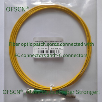
OFSCN® Standard Fiber Patch Cord: Standard high-precision patch cords for normal temperature environments, featuring extremely low insertion loss and excellent end-face geometry.
-
OFSCN® 120℃ Fiber Optic Patch Cord: Utilizes a special coating resistant to 120^\circ\text{C} and stainless steel tubing for protection, meeting the requirements for precision optical transmission in moderate industrial temperatures.
-
OFSCN® 300℃ Fiber Optic Patch Cord: Designed for extremely high-temperature environments (operating range -270^\circ\text{C} to 300^\circ\text{C} ), using special gold or polyimide fibers to ensure stable ferrule end-face contact during extreme temperature cycles.
Before performing any optical path connection, strictly adhering to the standard physical operating procedure of “Inspect first (microscope), clean second, connect third” is the core principle to avoid damaging optical components and ensure system performance.