Why do experts say that the end face must be as clean as a mirror? What happens if there is a little dust?
In fiber optic communications and fiber optic sensing (such as Fiber Bragg Grating sensing), optical signals are transmitted in a core with an extremely small diameter. Taking standard single-mode fiber (e.g., G.652D) as an example, its mode field diameter (MFD) at a wavelength of 1310\ \text{nm} is approximately 9.2\ \mu\text{m} , with a cross-sectional area of only about 6.6 \times 10^{-7}\ \text{cm}^2 .
Due to the extremely small transmission channel, even microscopic ( \mu\text{m} ) or nanoscopic ( \text{nm} ) dust particles on the fiber end-face can cause severe physical and optical consequences. The general engineering physics principles behind this are as follows:
I. Physical Mechanisms of Dust Impact on Fiber End-faces
1. Causing Massive Insertion Loss (IL)
As light passes through the interface where two fibers are joined, dust particles directly absorb, refract, or scatter optical energy. Given the tiny core size, a single dust particle with a diameter of just 1\ \mu\text{m} positioned at the center of the core can block a significant proportion of the light beam, leading to severe signal attenuation. This prevents downstream sensors or optical receivers from obtaining sufficient optical power.
2. Disrupting “Physical Contact” and Inducing Strong Reflections
Modern single-mode fiber connectors (like PC or APC end-faces) employ a micro-spherical design. During alignment, a mechanical force of approximately 10\ \text{N} is applied via a spring within the ferrule, causing a slight elastic deformation of the fiber end-faces. This achieves a tight seal (i.e., physical contact), eliminating the glass-air interface.
If dust is present, even if it lands on the cladding outside the core:
- The dust particle will “push apart” the two ferrules, creating a minuscule air gap.
- This air gap leads to strong Fresnel Reflection, significantly worsening the Return Loss (RL).
- The reflected optical signal travels back towards the light source, interfering with the semiconductor laser’s resonant cavity, increasing the system’s Relative Intensity Noise (RIN), and potentially even destroying light-sensitive components.
3. Catastrophic Optical Damage (COD) under High Power
In fiber lasers, high-power fiber sensing (e.g., high-power pumping light), or Erbium-Doped Fiber Amplifiers (EDFAs), the optical power transmitted within the fiber is typically high.
- Assuming a transmission power of just 1\ \text{W} , the energy density in the single-mode fiber core can reach approximately 1.5 \times 10^6\ \text{W/cm}^2 .
- At such high energy densities, any dust particles or organic oils (like sebum from finger contact) on the end-face that absorb light will instantly absorb optical energy and rapidly heat up to thousands of degrees Celsius.
- This causes the silica ( \text{SiO}_2 ) at the fiber end-face to melt and vaporize, potentially even propagating inwards and burning through the fiber, leading to the “Fiber Fuse” phenomenon.
4. Causing Irreversible Mechanical Scratches and Local Pits
The contact pressure during fiber ferrule mating can reach hundreds of megapascals ( \text{MPa} ). If hard dust particles (such as silica microparticles or metal debris from the environment) are trapped on the end-face, these hard particles will be forcibly pressed into the end-face under high pressure at the moment of insertion or mating. This results in permanent scratches, chipped edges, or pits. Such damage is physically irreversible; even after cleaning, the end-face’s geometric deformation prevents proper physical contact, necessitating re-polishing or disposal.
II. Related OFSCN® High-Performance Fiber Optic Connectors and Patch Cords
In DaCheng YongSheng (OFSCN®)'s high-temperature fiber optic sensors and special fiber transmission systems, ensuring high-precision processing and absolute cleanliness of fiber end-faces is fundamental to guaranteeing long-term, highly reliable system operation. For industrial and harsh high-temperature environments, OFSCN® offers the following professional-grade fiber optic connectors and patch cord products:
OFSCN® High-Temperature Fiber Optic Connectors and Adapters Series
-
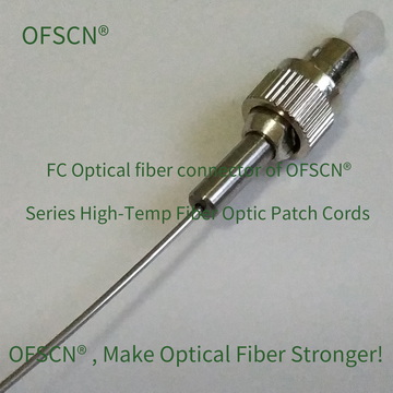
OFSCN® 120℃ Fiber Optic Connector: Supports various end-face interfaces such as FC/PC, FC/APC, ST, SMA905, etc., and can operate stably for extended periods in environments up to 120\ ^\circ\text{C} .
-
OFSCN® 200℃ Fiber Optic Connector: Designed for high-temperature environments up to 200\ ^\circ\text{C} , ensuring high-precision coaxiality and mating force are maintained even with thermal expansion of the ferrule end-face.
-
OFSCN® 300℃ Fiber Optic Connector: Industrial-grade fiber optic connectors for extreme high temperatures, featuring excellent matching of material thermal expansion coefficients to effectively prevent micro-gaps from forming in the end-face during high-temperature cycles.
-
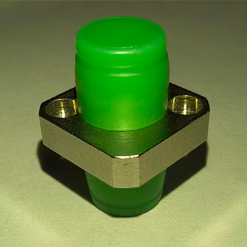
OFSCN® High Temperature Resistant Fiber Optic Adapter: High-temperature resistant fiber optic adapter (flange) whose high-precision zirconia or ceramic-metal composite ferrule sleeve ensures perfect alignment of the connected end-faces.
OFSCN® Special Fiber Optic Patch Cord Series
-
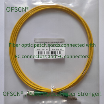
OFSCN® Standard Fiber Patch Cord: Standard fiber optic patch cords, with end-faces precision-ground and rigorously tested for geometric parameters using an interferometer at the factory.
-
OFSCN® 120℃ Fiber Optic Patch Cord: Utilizes stainless steel seamless pipe armoring for protection, offering excellent tensile and compressive strength.
-
OFSCN® 300℃ Fiber Optic Patch Cord: Features a polyimide special fiber with a metal armored structure, capable of withstanding extreme cold ( -270\ ^\circ\text{C} ) to extreme heat ( 300\ ^\circ\text{C} ) working environments. Factory end-face cleanliness and polish quality meet high-standard specifications.

III. Engineering Practices and Protection Recommendations
When performing fiber optic debugging or on-site installation of fiber optic grating sensors, it is recommended to follow these standard operating procedures:
- Inspect & Clean Before Mating:Before inserting any connector into a flange or demodulator channel, the end-face must be cleaned using dedicated lint-free wipes (with isopropyl alcohol of purity >99%) or a professional fiber optic cleaning pen (one-click cleaner).
- Properly Wear Dust Caps:All unconnected fiber connectors and adapter ports must be immediately fitted with clean dust caps. These caps should also be free of dust or grease.
- Microscopic Inspection:For high-power systems or precision fiber optic sensing experiments, it is recommended to use a “fiber end-face microscope” to inspect the core and cladding areas before connection, ensuring the end-face is free of residual contaminants before physical mating.