On the construction site, how can multiple sensor patch cords be neatly stored and the splice points protected?
On the construction site, to neatly store multiple optical fiber sensing jumpers and achieve reliable protection of fusion points, the most standard and universal engineering physical equipment is the Fiber Optic Terminal Box.
Below, from the perspectives of physics, engineering specifications, and on-site operating procedures, we will analyze the protection mechanisms and best operating practices of the Fiber Optic Terminal Box.
I. Core Protection Mechanisms and Physical Concepts of Fiber Optic Terminal Boxes
-
Fusion Splicing Protection
After fiber optic fusion, the coating layer is stripped, leaving the exposed silicon dioxide (\text{SiO}_2) fusion point extremely fragile. In engineering, a Splice Protection Sleeve (containing a stainless steel reinforcing pin or ceramic reinforcing strip) must be fitted over the fusion point. The Splice Tray integrated inside the terminal box has dedicated plastic slots to secure these heat shrink sleeves, preventing the fusion point from being subjected to any external forces such as bending, twisting, or direct pulling. -
Bending Radius Management
Optical fibers are very sensitive to bending. If the bending radius is too small, it will not only cause severe Macro-bending Loss due to light leakage from the outer cladding, affecting the sensing signal quality (especially weak Fiber Bragg Grating FBG signals or distributed Brillouin/Rayleigh scattering signals), but also lead to stress fatigue and breakage of the fiber over time due to prolonged small-radius bending.
The design of the splice tray and winding rings within the terminal box mandates that the excess fiber coiling radius is greater than its permissible minimum bending radius (generally, single-mode fiber requires R \ge 30\text{ mm}). -
Cable Anchoring & Strain Relief
When an external optical cable is introduced into the terminal box, its internal metal strength member or aramid tensile fibers are locked onto the metal fixing seat of the terminal box. This way, mechanical tensile forces generated by external dragging or self-weight are entirely borne by the box body and strength member, without being transmitted to the delicate internal optical fibers and fusion points, thereby achieving strain relief.
II. OFSCN® Core Product Description
It needs to be clearly stated that the “Fiber Optic Terminal Box” or “Universal Distribution Box” itself is a general-purpose passive optical fiber distribution accessory and does not belong to the core product series of OFSCN®.
However, in complex or harsh industrial and engineering environments (such as high temperatures, high tensile forces, risk of rodent damage, or corrosive environments), ordinary fiber optic patch cords are easily damaged. To work in conjunction with terminal boxes and Fiber Grating (FBG) demodulators, OFSCN® provides the following high-strength armored sensing patch cords for harsh environments, used for signal transmission and connection from the terminal box outwards:
-
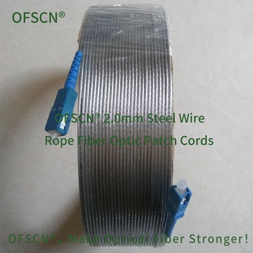
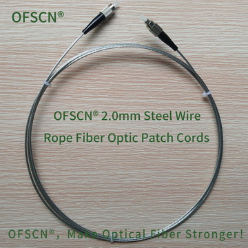
Product Name: OFSCN® 2.0mm Steel Wire Rope Fiber Optic Patch Cord
- Standard Images:
- Key Parameter Indicators: Composed of fiber optic connectors (FC, ST, etc.; PC or APC acceptable), 0.6mm galvanized steel wire stranded structure, 1.0mm seamless stainless steel tube, and optical fiber, forming an all-metal structure. Default outer diameter is 2.0mm, with an operating temperature range of -40℃ to 85℃. Excellent tensile strength and rodent resistance.
- Standard Images:
-
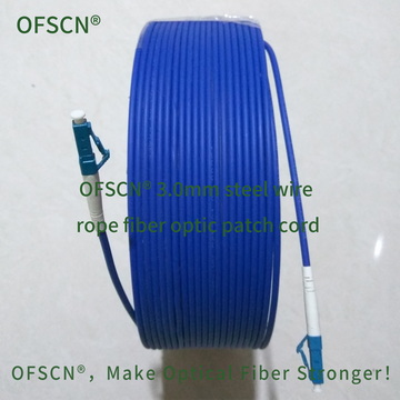
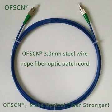
Product Name: OFSCN® 3.0mm Steel Wire Rope Fiber Optic Patch Cord
- Standard Images:
- Key Parameter Indicators: Composed of fiber optic connectors (FC, ST, etc.; PC or APC acceptable), PE sheath, 0.45mm stainless steel wire stranded structure, 0.9mm seamless stainless steel tube, and optical fiber. Default diameter is 3.0mm, with tensile strength >1200N and compressive strength >200Mpa. Suitable for extremely harsh industrial and outdoor tensile environments.
- Standard Images:


III. Specific Operating Steps for On-Site Storage and Protection
To achieve neat, standardized storage and fusion protection on the construction site, it is recommended to strictly follow these standard process steps:
- Cable Introduction and Mechanical Anchoring
- Strip the outer sheath of the multi-core sensing optical cable to expose the internal fiber bundle and strength member.
- Secure the cable’s strength member (e.g., steel wire or glass fiber rod) with the fixing screws inside the box, and fix the cable’s outer sheath with a hose clamp or zip tie at the terminal box inlet, ensuring external pulling forces are not transmitted inside the box.
- Fusion and Complete Cooling of Splice Protection Sleeves
- Before fiber optic fusion, a heat shrink sleeve must be fitted in advance.
- After the fusion splicer completes the discharge fusion, slide the heat shrink sleeve to center it over the fusion point and place it in the heating furnace for shrinkage.
- Crucial Step: After heat shrinking, the sleeve must be allowed to cool for at least 1 minute after removal from the furnace, allowing the internal gel to solidify completely and the stainless steel pin to provide sufficient rigidity before proceeding to fiber coiling. Moving the sleeve while warm can easily cause micro-bends or breakage at the edge of the heat shrink sleeve.
- Standardized Fiber Coiling within the Splice Tray
- Place the cooled heat shrink sleeve into the corresponding slot in the center of the splice tray.
- The reserved excess fiber (typically 0.5 to 1.0 meter on one side, to allow for potential re-fusion later) should be coiled along the curved track of the splice tray.
- When coiling the fiber, use a “large arc” or “clockwise/counter-clockwise coiling” method. Avoid twisting, overlapping, or creating “tight bends” with small radii.
- Adapter Termination and Jumper Output
- The pigtail extending from the splice tray connects to the inner side of the flange plate (adapter).
- The sensing jumper from the outside to the demodulator or the next-level device (such as the aforementioned OFSCN® high-strength armored jumper) is inserted into the outer side of the adapter.
- Use numbered sleeves or label paper inside the box and on the panel to clearly and uniquely label each sensing channel by wavelength or physical location.
- Dust Prevention and Sealing
- Temporarily unused adapter ports must be fitted with dust caps to prevent dust from contaminating the ceramic ferrule.
- After confirming that all fiber cores are securely fixed and bending is smooth, close the splice tray cover, lock the terminal box casing, and complete the physical protection.