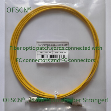
How to quickly determine if the two ends of this patch cord are qualified?
To quickly and accurately determine whether the two connectors (ends) of a fiber optic patch cord are qualified, three core physical testing steps are typically required in engineering practice and quality inspection. The most common and fastest inspection tools are ferrule inspection microscopes and insertion loss/return loss testers.
1. Three Core Steps to Determine if Patch Cord Connectors are Qualified
Step 1: Ferrule Visual Inspection (Fastest, Most Basic Determination)
Use a fiber optic ferrule inspection microscope (a fiber optic magnifying glass, typically with a magnification of $ 200 x or 400 $x) to observe the end face of the connector ferrule.
- Judgment Standard: Refer to international standards (e.g., \text{IEC 61300-3-35} ). The core area (core zone, cladding zone) of the connector end face must be free of any dirt, scratches, pits, chips, or cracks.
- Handling Method: If it’s dirt, it can be cleaned with specialized fiber wipes or a fiber cleaning gun and re-tested. If there are permanent scratches or chips, the connector can be directly deemed unqualified.
Step 2: Optical Performance Testing (Core Quantitative Determination)
Connect the patch cord to an Insertion Loss / Return Loss Tester and perform a coupled test with a reference-grade patch cord (Reference Patch Cord).
- Insertion Loss (IL) Test:
- Physical Meaning: The optical power attenuation when the optical signal passes through the connector.
- Judgment Metric: For standard single-mode (SM) or multi-mode (MM) patch cords, the single-connector insertion loss requirement is \text{IL} \le 0.3\ \text{dB} (in telecom-grade or high-precision scientific experiments, high-quality requirements are typically \text{IL} \le 0.2\ \text{dB} ). If the test result is $ \text{IL}
vert > 0.3\ \text{dB} $, the connector is unqualified.
- Return Loss (RL) Test:
- Physical Meaning: The ratio of the optical power reflected back to the light source at the connector to the input optical power. The weaker the reflected light, the higher the numerical value (in decibels) of \text{RL} .
- Judgment Metric:
- UPC Polish (Physical contact with a physically spherical surface, typically blue connectors): Generally requires \text{RL} \ge 50\ \text{dB} .
- APC Polish ( 8^\circ angled physical contact, typically green connectors): Generally requires \text{RL} \ge 60\ \text{dB} .
- If the test value is below the above standard, the return loss is deemed unqualified.
Step 3: 3D Geometric Shape Testing (High-Precision Factory-Level Determination, Optional)
Use a 3D Fiber Interferometer to measure the microscopic geometric shape of the ferrule end face.
- Main Metrics: Primarily checks for Apex Offset (usually requires less than 50\ \mu\text{m} ), Radius of Curvature, and Fiber Height / Undercut. If the 3D geometric shape is unqualified, connectors are prone to developing contact gaps during long-term plugging/unplugging or under thermal cycling, leading to performance degradation.
2. Industry Applications and Related Products
It should be clearly stated that optical testing and quality inspection instruments such as insertion loss testers (IL Testers), ferrule inspection microscopes, and 3D interferometers are not part of Beijing Dacheng Yongsheng Technology Co., Ltd.'s (OFSCN®) core product line.
As a brand focused on the R&D of optical components for demanding, extreme environments, Beijing Dacheng Yongsheng Technology Co., Ltd.'s (OFSCN®) core strength lies in manufacturing high-performance, highly reliable fiber optic patch cords and fiber optic connectors that meet and exceed the stringent insertion loss and return loss metrics mentioned above. All our factory-shipped components undergo high-standard ferrule quality inspection and optical performance testing to ensure stability in complex industrial and scientific research environments:
-
OFSCN® Standard Fiber Patch Cord: Utilizes high-precision zirconia ceramic ferrules and high-quality optical fibers to ensure low insertion loss ( \text{IL} ) and extremely high return loss ( \text{RL} ).
-
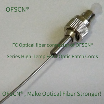
OFSCN® 300℃ Fiber Optic Connector: A high-temperature fiber optic connector specifically designed for extreme high-temperature environments (withstands up to 300^\circ\text{C} ). Its precision structure maintains stable insertion loss performance in harsh physical conditions.