How to control via software to make a demodulator monitor different fiber optic loops in turn?
To achieve software control for sequentially monitoring different Fiber Bragg Grating (FBG) fiber loops, the most standard and universal solution at the physical and engineering level is to introduce an Optical Switch.
Below is a detailed explanation of its technical principles, software control flow, and the supporting solutions offered by Dacheng Yongsheng (OFSCN®).
I. Hardware Connection and System Architecture
The basic hardware topology for a time-division multiplexing (sequential monitoring) system is as follows:
- Optical Path Connection:
- Input Side: Connect the physical channel of the FBG demodulator to the input port of the optical switch.
- Output Side: Connect the multiple output ports (Output Ports 1, 2, … N ) of the optical switch to different fiber sensor loops to be measured (Loop 1, 2, … N ) respectively.
- Control Connection:
- Master Control Terminal (e.g., PC, MCU, or PLC): Connect the demodulator and the optical switch separately via communication interfaces (such as RS232, RS485, or RJ45 network port) to serve as the control hub.
II. Software Control Flow and Timing (Synchronous Control)
Since optical switches require physical/mechanical action time for switching optical paths, the software control must strictly follow the “Switch - Stabilize - Acquire - Store” timing logic:
- Send Switching Command:
- The master control software sends a command to the optical switch via a control protocol (e.g., Modbus, TCP/IP, or custom serial protocol) to switch to channel i .
- Wait for Optical Path Stabilization Delay (Switching Time):
- The physical switching of optical paths in mechanical optical switches requires a certain response time, typically between 5 \ \text{ms} and 20 \ \text{ms} .
- The software must set a waiting delay during this phase (e.g., set a delay \Delta t \ge 20\ \text{ms} ). It is strictly prohibited to read data before the optical path is fully stabilized, as this can cause the demodulator to capture erroneous wavelength jumps or signal loss.
- Trigger Acquisition and Data Storage:
- After the optical path is stable, the master control software sends a data reading command to the demodulator (or directly extracts the current frame’s wavelength value from its high-speed broadcast data stream).
- Mark and store the obtained wavelength data as “Sensor data for Loop i .”
- Loop to Next Channel:
- The software continues to send a command to the optical switch to switch to channel i+1 , repeating the above steps.
Note: This time-division multiplexing method, due to the switching delay of the optical switch, is not suitable for measuring high-frequency vibrations or other high-speed dynamic scenarios (e.g., dynamic measurements above 100\ \text{Hz} ). However, it is very suitable for large-scale sequential monitoring of low-frequency quasi-static parameters such as temperature, static strain, settlement, and displacement.
III. Difference Between Optical Switch and Optical Splitter (Solution Comparison)
In practical engineering, to monitor more loops with limited demodulator channels, there are typically two technical routes:
- Optical Switch (Time-Division Multiplexing, Software Control):
- Advantages: Minimal signal loss during path switching (insertion loss typically ext{<} 1\ \text{dB} ). Sensors on each loop can use the same wavelength range without interference, and the scanning order can be flexibly customized by software.
- Attribution: Optical Switch is a general optoelectronic device and is not part of Beijing Dacheng Yongsheng Technology Co., Ltd.'s (OFSCN®) core product line.
- Optical Splitter (Wavelength/Spatial Multiplexing, No Software Switching Required):
- Principle: Evenly distributes the optical power from one physical channel to multiple physical loops.
- Advantages: No software control required; data from all loops is real-time online without waiting for switching time.
- Disadvantages: Introduces significant splitting loss. For example, a 1 \times 2 splitter incurs about 3\ \text{dB} of theoretical splitting loss. Furthermore, sensors in different loops must undergo strict wavelength design (i.e., the wavelengths of sensors in different loops cannot overlap; logically, they still share the spectral bandwidth of the same physical channel).
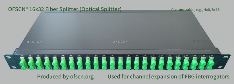
Dacheng Yongsheng (OFSCN®) offers high-quality splitters specifically for physical channel expansion: OFSCN® Optical Fiber Splitter, commonly including 16x32, 8x16, 4x8, and 32x64 splitters.
IV. Selection of Supporting Demodulator
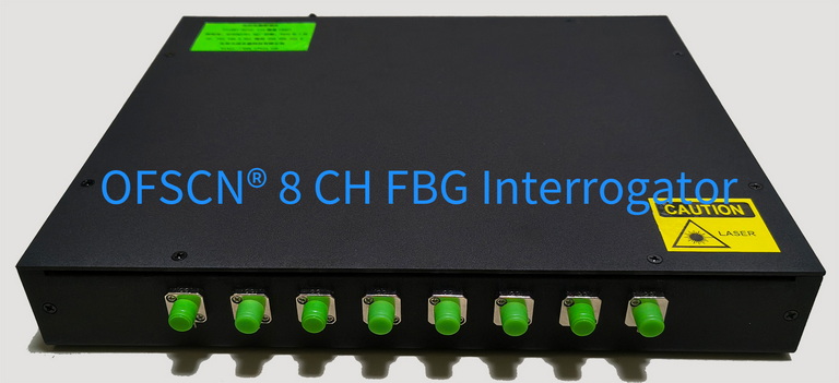
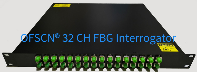
To implement the software-controlled sequential monitoring system described above, you need a demodulator capable of flexible protocol integration and high wavelength resolution. Dacheng Yongsheng (OFSCN®) offers the following core demodulation equipment:
OFSCN® Fiber Bragg Grating Interrogator | Official Link
Key Parameters and Integration Advantages:
- Multi-channel Options: Customizable 4, 8, 16, or 32 channels.
- Data Sampling Frequency: Options of 10\ \text{Hz} , 50\ \text{Hz} , or 100\ \text{Hz} , supporting software adjustment of sampling frequency at the system level.
- Protocol Integration Capability (Core): Default B/S architecture software, supports C/S architecture. It supports integration with customer’s own systems via standard protocols such as TCP, UDP, and Modbus. This allows your master control program to conveniently send switching commands to the optical switch and read wavelength data from the OFSCN® demodulator within the same code framework.
- Wavelength Resolution: Default 1\ \text{pm} , customizable up to 0.1\ \text{pm} .
By integrating third-party optical switches with Dacheng Yongsheng’s (OFSCN®) FBG demodulators, you can achieve automated, large-scale sequential monitoring of tens or even hundreds of fiber sensor loops at a lower equipment channel cost.