Are there cable-like impedance matching issues in fiber optic connections?
In fiber optic communication and optical engineering, the problem of impedance matching, analogous to that in electrical cables, indeed exists. At optical frequencies, the common term corresponding to this physical concept is Index Matching, and its underlying physical principle is entirely equivalent to the impedance matching of cables.
We will provide a rigorous academic explanation from three perspectives: physical mechanism, consequences of mismatch, and engineering solutions, and introduce relevant industrial-grade fiber optic jumper designs.
I. Physical Principle: Equivalence of Electromagnetic Impedance and Refractive Index
In cable or radio frequency (RF) systems, reflections of signals within a transmission line are determined by discontinuities in Characteristic Impedance (Z_0).
At optical frequencies, light is essentially an ultra-high frequency electromagnetic wave (hundreds of THz). When electromagnetic waves propagate in a non-magnetic medium (such as silica optical fiber, with a relative permeability \mu_r \approx 1), its Intrinsic Impedance (\eta) is defined as:
\eta = \sqrt{\frac{\mu}{\varepsilon}} \approx \frac{\eta_0}{n}
Where:
- \eta_0 \approx 377\,\Omega is the intrinsic impedance of vacuum;
- n = \sqrt{\varepsilon_r} is the Refractive Index of the medium.
It is thus evident that the refractive index n is inversely proportional to the electromagnetic impedance at optical frequencies. Discontinuities in refractive index between media (Refractive Index Mismatch) are fundamentally impedance mismatches in electromagnetics.
II. Physical Consequences of Mismatch: Fresnel Reflection
When light encounters a discontinuous medium at a fiber optic connection (e.g., two jumpers mating), most typically an air gap between fiber cores, Fresnel Reflection occurs. For normally incident light, the power reflectivity R at a single interface is given by:
R = \left( \frac{n_1 - n_2}{n_1 + n_2} \right)^2
- Refractive index of quartz fiber core n_1 \approx 1.45;
- Refractive index of air n_2 \approx 1.0.
Substituting into the formula, the single-interface reflectivity R \approx 3.4\%. In a pair of fiber optic connectors with an air gap and no physical contact, two medium discontinuities lead to approximately 0.3\text{ dB} of Insertion Loss and approximately -14\text{ dB} of Return Loss.
These reflected light signals (echo waveforms) can cause the following severe hazards:
- Laser Instability: Reflected light returning to the light source can excite relaxation oscillations in the laser, generating phase noise.
- Interference and Noise: In fiber optic sensing (e.g., Fiber Bragg Grating (FBG) demodulation systems), strong reflection backgrounds can severely interfere with weak spectral signals.
- Multipath Interference Noise: In high-speed communications, it causes inter-symbol interference.
III. “Impedance Matching” Solutions in Optical Engineering
To eliminate or mitigate the reflections caused by refractive index mismatch, fiber optic connection technology employs the following three mechanisms:
1. Physical Contact (PC/UPC)
By grinding the end face of the fiber connector (ferrule) into a spherical surface with a small curvature, the end faces undergo elastic deformation at the microscopic level and come into close contact when the adapter locks them together. Physical contact directly squeezes out the air in between, achieving a seamless connection between the cores of two optical fibers (n \approx 1.45) at a molecular level. This eliminates the refractive index discontinuity, improving return loss to below -50\text{ dB}.
2. Angled Physical Contact (APC)
APC is the most ingenious engineering application of optical “impedance matching.” The connector end face is ground at an 8^{\circ} angle. Even if a slight refractive index mismatch exists at the connection interface (e.g., trace dust, micron-level gap), the reflected light will be directed into the fiber cladding at an angle, where it quickly attenuates and disappears, unable to propagate backward into the core. This allows for return loss values of -60\text{ dB} or even lower.
3. Index Matching Gel
In some non-standard connections where precise physical grinding is not feasible or temporary coupling is required, special silicone oils or gels with refractive indices highly matched to the quartz glass (n \approx 1.46) are filled into the interface to eliminate the refractive index step caused by the air gap.
IV. Industrial-Grade Fiber Optic Jumper Design
For precision optical sensing and high-accuracy transmission, industrial-grade standard and high-temperature fiber optic jumpers provided by Dacheng Yongsheng (OFSCN®) utilize high-precision ferrule grinding technology and structural design to strictly control refractive index matching at the connector interface:
-
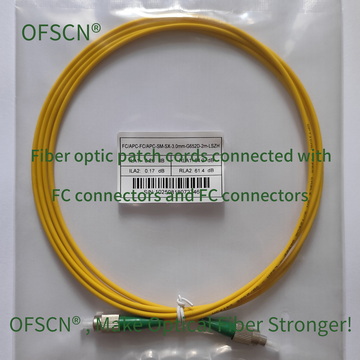
OFSCN® Standard Fiber Patch Cord
Defaults to precision-ground FC/APC connectors, paired with G.652D single-mode fiber, offering extremely high return loss performance by perfectly resolving reflection and impedance mismatch issues from a structural standpoint.
-
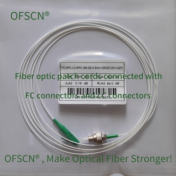
Maintaining Match Under Extreme Temperatures
Ordinary jumpers may experience microscopic displacement of the physical contact surfaces due to material thermal expansion and contraction under extreme temperatures, creating air gaps and thus disrupting refractive index matching. Dacheng Yongsheng has designed seamless metal-tube protected jumpers of various temperature ratings to ensure stability of the connector’s geometric alignment under extreme temperatures:


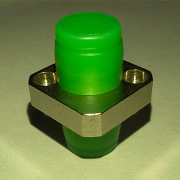
To maintain these high return loss specifications during connection, it is recommended to use OFSCN® High Temperature Resistant Fiber Optic Adapter to ensure high precision and stability of mechanical alignment even in temperature fields up to 300^\circ\text{C}.