Why must the connector of a PM jumper be aligned at a specific angle when inserted?
In Polarization-Maintaining (PM) fiber optic communication and sensing systems, the connectors of PM patch cords (such as the commonly used FC/PC or FC/APC) must be aligned to a specific angle when inserted into adapters (ferrules). This requirement is determined by the physical properties of birefringence and the optical alignment precision of the PM fiber.
Below, we rigorously analyze the scientific principles of “Keyway Alignment” from three perspectives: physical mechanisms, mathematical principles, and engineering implementation:
I. Physical Mechanism: Birefringence and Polarization Axes of PM Fiber
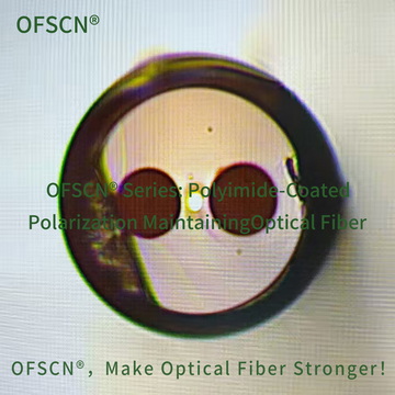
Polarization-Maintaining Fiber (PMF) can maintain the polarization state of light due to its asymmetric internal physical structure. Taking the classic Panda-type PM Fiber as an example:
- Structural Asymmetry: Two stress-applying parts (SAPs) with different thermal expansion coefficients are symmetrically embedded on both sides of the fiber core.
- Stress-induced Birefringence: Due to the difference in thermal expansion coefficients of the materials, the fiber core is subjected to asymmetric lateral stress during cooling. This results in a difference in refractive index in the orthogonal directions (i.e., birefringence: B = |n_x - n_y|).
- Fast & Slow Axis: This creates two orthogonal polarization axes within the fiber. The axis with the larger refractive index is called the Slow Axis, and the axis with the smaller refractive index is called the Fast Axis.
When linearly polarized light is coupled into the fiber along one of the polarization axes (usually the slow axis), due to the strong birefringence effect between the two axes, it is very difficult for the light to couple from one polarization state to another, even if the fiber is disturbed by micro-bending, vibration, or environmental temperature changes, thus achieving “polarization preservation.”
II. Mathematical Principle: Degradation of Polarization Extinction Ratio (PER) due to Angular Deviation
When two PM fibers are spliced, or a PM fiber is spliced to a laser, if the polarization axes of both ends (e.g., slow axis to slow axis) are not perfectly aligned but have an angle \theta, the polarized light will split and cross-couple at the connection interface.
The degradation of the transmitted light’s polarization state can be quantified by the Polarization Extinction Ratio (PER or ER), according to polarization optics and Malus’s Law. Its theoretical limit formula is:
\text{PER} \approx -10 \log_{10} (\tan^2 \theta)
- Angular Deviation \theta = 0^\circ: Ideal state, infinite extinction ratio (no energy leakage to the other orthogonal axis).
- Angular Deviation \theta = 1^\circ: Theoretical maximum extinction ratio is approximately 35 \text{ dB}.
- Angular Deviation \theta = 2^\circ: Theoretical maximum extinction ratio drops sharply to approximately 29 \text{ dB}.
- Angular Deviation \theta = 5^\circ: Theoretical maximum extinction ratio degrades to 21 \text{ dB}, at which point the polarization-preserving performance is significantly degraded.
In practical optical sensing (such as fiber optic gyroscopes, coherent optical communication), it is usually required that the PER of the connected system remains above 20 \sim 30 \text{ dB}. This requires the angular deviation \theta during connector mating to be strictly controlled within \pm 1.5^\circ or even \pm 1.0^\circ.
III. Engineering Implementation: Key and Keyway
To enable users to achieve micro-degree angular alignment during actual insertion and removal operations without the need for complex calibration instruments, PM connectors incorporate a Keyway Alignment mechanism:
- Key: The metal plug of FC-type PM connectors has a raised metal pin on the outside, which is the key.
- Precise Factory Alignment (Active Alignment): During the production of PM patch cords, engineers use high-precision PM axis alignment instruments to observe the geometric structure of the stress zones on the fiber end face. They rotate the fiber to align the fiber’s polarization axis (defaulting usually to the slow axis) with the key of the connector plug. After alignment, the fiber, ferrule, and housing are fixed with epoxy resin.
- Adapter Slot (Keyway): The corresponding flange (adapter) has a locating slot. When the patch cord is inserted, the plug can only be fully inserted and locked when the key completely slides into the slot, thereby forcing the spatial geometric alignment of the fiber polarization axes at both ends.
Common Industry Sizes (Narrow Key and Wide Key):
In FC PM connectors, there are two standard key widths that must strictly match the adapter:
- Narrow Key (Type R): Key width is approximately 2.02 \text{ mm}.
- Wide Key (Type N): Key width is approximately 2.14 \text{ mm}.
If a narrow key plug is forcibly inserted into a wide key flange, it will result in excessive rotational tolerance, causing the extinction ratio to fluctuate severely or degrade.
IV. Related Specialty Fiber and Patch Cord Products
In OFSCN®'s series of high-temperature and specialty fibers, we offer high-precision PM products to meet polarization-holding demands in extreme environments:
-
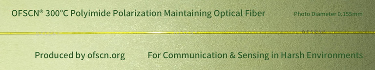
Product Name: OFSCN® 300℃ Polyimide Panda-type PM Optical Fiber
Utilizes a high-precision Panda stress structure design, capable of maintaining stable birefringence and extremely high physical polarization-holding characteristics even in extreme temperatures ranging from -200^\circ\text{C} to 350^\circ\text{C}.-
Standard Images:
-
-
Customized Products: OFSCN® 120℃ Fiber Optic Patch Cord and OFSCN® 200℃ Fiber Optic Patch Cord both support custom PM patch cords. We employ precise alignment processes at the factory to ensure that the extinction ratio and plug-in stability of our PM connectors meet the stringent requirements of scientific research and precision engineering in harsh industrial or experimental environments.