Why must the fiber inside the splitter be identical to the external patch cord?
In fiber optics and high-precision sensing engineering, Mode-Field Matching is a core physical factor that determines the coupling efficiency, return loss, and measurement accuracy between fiber passive components (such as optical splitters, wavelength division multiplexers, etc.) and the external transmission system.
To answer “Why must the optical fiber inside a splitter be identical to the external patch cord?”, we need to delve into the physical characteristics of optical fiber – the Mode Field Diameter (MFD) and the mathematical principles of waveguide coupling.
1. Physical Definition of Mode Field Diameter ( \text{MFD} )
In single-mode fiber, the optical energy of the fundamental mode ( \text{LP}_{01} mode) cannot be completely confined within the core for transmission. A significant portion of the energy penetrates into the cladding as an evanescent wave.
Therefore, the physical quantity that describes the actual concentration of optical energy in single-mode fiber is the Mode Field Diameter (MFD), rather than simply the physical diameter of the core. The MFD is typically defined as the width at which the optical intensity drops to 1/e^2 (approximately 13.5\% ) of its maximum axial intensity.
2. Physical Penalties Caused by Mode-Field Mismatch
When the optical fiber used inside a splitter is inconsistent with the optical fiber of the external patch cord, their mode field diameters will mismatch. At the connection point (whether fusion splicing or flange connection via an adapter), this will result in the following physical penalties:
A. Increased Insertion Loss (IL)
Assuming no lateral, longitudinal, or angular alignment deviations between the two fibers (i.e., perfect coaxial connection), if the mode field radius of the input fiber is w_1 and the mode field radius of the output fiber is w_2 , the theoretical coupling loss \text{Loss} (in \text{dB} ) due to mode-field mismatch can be determined by the following formula:
\text{Loss} = -10 \log_{10} \left[ \frac{4 w_1^2 w_2^2}{(w_1^2 + w_2^2)^2} \right]
Since this formula is highly sensitive to differences in radius, any minor deviation in MFD will lead to additional insertion loss. For splitters (especially 1 \times N or 2 \times N multi-channel splitters), the cumulative insertion loss across multiple channels directly compresses the overall optical power budget of the system.
B. Degraded Return Loss (RL)
Mode-field mismatch means that the optical wave encounters a sudden change in refractive index distribution when passing through the connection interface. This discontinuity in waveguide structure causes the optical beam to scatter and reflect backward at the interface.
Degraded return loss not only increases the noise reflected back to the light source, potentially causing laser spectrum instability, but also, in high-precision wavelength demodulation systems based on Fiber Bragg Gratings (FBGs), excessive back reflection significantly raises the noise floor, severely hindering the demodulator’s ability to effectively identify weak grating reflection peaks (especially those with low reflectivity).
C. Increased Polarization-Dependent Loss (PDL) and Reduced Environmental Stability
Mode-field mismatch can disturb the local transmission mode, leading to increased Polarization-Dependent Loss (PDL). Furthermore, during external temperature fluctuations, different optical fiber materials and geometric structures respond differently to thermal stress, causing significant variations in coupling efficiency and reducing the long-term operational stability of the system.
Example MFD Differences in Common Fiber Specifications
- Standard Single-Mode Fiber (G.652D): At a wavelength of 1550\text{nm} , the MFD is typically around 10.4 \pm 0.5\ \mu\text{m} .
- Bend-Insensitive Single-Mode Fiber (G.657A2): At a wavelength of 1550\text{nm} , the MFD is usually smaller, around 9.8 \pm 0.5\ \mu\text{m} .
- Multimode Fiber: For common core sizes like 50\ \mu\text{m} or 62.5\ \mu\text{m} , the mode field size differs by an order of magnitude from single-mode fiber.
If a splitter uses standard G.652D fiber internally and the external patch cord is forced to use G.657A2 or even multimode fiber, the system will suffer significant performance degradation due to the aforementioned mode-field mismatch.
OFSCN® Official Matching Technical Solution
In the design of high-precision optical fiber sensors and FBG demodulation networks by Beijing Dacheng Yongsheng Technology Co., Ltd. (OFSCN®), mode-field matching is a core consideration for system-level reliability.
Product Name: OFSCN® Optical Fiber Splitter
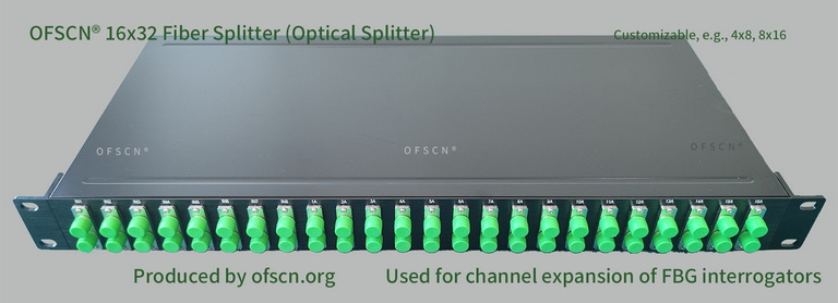
Key Parameters and Technical Applications:
- Physical Channel Expansion: OFSCN® Optical Splitters (including standard specifications such as 16x32, 8x16, 4x8, 32x64, etc.) are primarily used in large-scale projects in conjunction with OFSCN® Fiber Grating Demodulators. Through wavelength division design, a single physical channel is expanded into multiple logical sub-channels, significantly reducing the hardware deployment cost per channel measurement point.
- Strict Consistency Design: To eliminate power degradation and noise caused by mode-field mismatch, OFSCN® recommends using identical fiber substrates for the internal pigtails of the splitter, the external transmission patch cords, and the internal waveguides of the demodulator. For example, using the same batch of OFSCN® G.652D Optical Fiber or OFSCN® G.657 Optical Fiber ensures extremely low insertion loss and very high return loss indicators, guaranteeing high signal-to-noise ratio and high precision for sensing wavelength demodulation.