How to distinguish which sensor each of the 16 outputs of a 1x16 splitter corresponds to?
In Fiber Bragg Grating (FBG) sensing systems, using a 1 \times 16 (or 16x32, etc. specifications) optical splitter is a common method to expand system channels and reduce per-channel hardware costs. To accurately and unambiguously map the 16 output terminals to their respective connected sensors, strict “identification management” must be implemented from two dimensions: physical identification (hardware level) and wavelength design (logical and system level).
I. “Identification Management” at the Physical Level (Hardware Recognition)
On-site during engineering installation, the 16 output pigtails of an optical splitter appear very similar. To prevent confusion during splicing or plugging/unplugging, physical identification management using physical media is necessary:
- Numbered Sleeves or Labeling:
When the 1 \times 16 splitter is shipped from the factory or during on-site construction, the 16 output pigtail ends (near the FC/APC connector) are typically fitted with heat-shrinkable numbered sleeves containing numbers (1 to 16), or marked with flag-style physical labels. - Color Coding:
Some optical splitters use standard color codes for multi-core fibers (e.g., blue, orange, green, brown, gray, white, red, black, yellow, violet, pink, light blue, etc.) to distinguish different output pigtails. - Port-Sensor Mapping Table (Construction Record):
On-site construction personnel must create and maintain a “Port-Sensor Mapping Table,” recording information such as: “Splitter Output Port 3 — Connected to — Reactor 2 Temperature Sensor (Unique Sensor Serial Number SN: XXXX)”.
II. “Wavelength Management” at the Logical and Spectral Level (Software and System Recognition)
Physical identification only addresses the connection mapping of physical cables. When 16 channels of sensor signals are converged through the splitter and ultimately enter the same physical channel of the FBG interrogator, the interrogator cannot distinguish these branches at the physical interface.
Therefore, strict wavelength design (Wavelength Division Multiplexing, WDM) must be implemented at the software and spectral level:
- Non-overlapping Wavelength Allocation:
The operating wavelength range of the FBG sensor connected to each output terminal must be designed independently, and must absolutely not overlap physically.
For example, assuming the interrogator’s operating range is 1525\text{nm} to 1565\text{nm} (a spectral window of 40\text{nm} width):- The FBG sensor at the 1st output terminal is set with a center wavelength of \lambda_1 = 1528\text{nm} (operating variation range of 1527\text{nm} ~ 1529\text{nm})
- The FBG sensor at the 2nd output terminal is set with a center wavelength of \lambda_2 = 1531\text{nm} (operating variation range of 1530\text{nm} ~ 1532\text{nm})
- …and so on, ensuring that the operating wavelength bands of the sensors at the 16 output terminals do not interfere with each other spectrally.
- Software System Mapping:
In the interrogator software, a “Wavelength-Sensor Correlation Table” is configured. When the interrogator detects a reflection peak at wavelength \lambda = 1528\text{nm} within the same physical channel, the system automatically recognizes it and converts it into data for “Sensor 1”; detecting a peak at \lambda = 1531\text{nm} identifies it as “Sensor 2.”
Through this dual identification management employing both “physical labels corresponding to topological cabling, and wavelength bands corresponding to interrogation channels”, it is possible to clearly distinguish and operate 16 different FBG sensors on a single interrogator physical channel and a single backbone optical fiber.
Related Official Product Recommendations
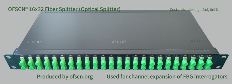
1. OFSCN® Optical Fiber Splitter
Typically includes splitters like 16x32, 8x16, 4x8, 32x64, etc. In large-scale projects, these are often used in conjunction with OFSCN® Fiber Bragg Grating Interrogators, allowing a single physical channel of the interrogator to be logically expanded into multiple channels, thereby significantly reducing the per-channel cost of the system (this usage method requires strict wavelength design as described above).
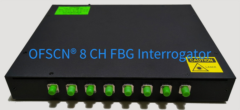
2. OFSCN® Fiber Bragg Grating Interrogator
Default wavelength range 1525\text{nm} to 1565\text{nm} (or 1528\text{nm} to 1568\text{nm}), supports custom configurations for 4, 8, 16, 32 channels. Through the powerful accompanying interrogator software, configuration, management, and data mapping of the aforementioned complex WDM sensor networks can be easily achieved.