How to calculate if the remaining optical power after the splitter is sufficient for the demodulator to recognize?
In a Fiber Bragg Grating (FBG) sensing system, determining if the remaining optical power after a splitter is sufficient for demodulator recognition is a standard Optical Power Budget (OPB) calculation problem.
Since Fiber Bragg Grating sensors operate in reflection mode, the optical signal undergoes “round-trip” transmission within the system. This means that in addition to the intrinsic reflection loss of the FBG itself, all other optical path components (including splitters, transmission fibers, connectors, etc.) must have their losses calculated twice.
Below is a complete general engineering calculation method and quantitative physical analysis:
1. Basic Optical Power Budget Calculation Formula
To ensure the demodulator can stably recognize the reflection wavelength of the FBG, the actual optical power received by the demodulator, P_{\text{rec}} , must be greater than the demodulator’s minimum detection sensitivity, P_{\text{min}} , plus a system safety margin.
The total system loss, L_{\text{total}} (in \text{dB} ), is calculated as follows:
L_{\text{total}} = 2 \times L_{\text{splitter}} + 2 \times L_{\text{fiber}} + 2 \times L_{\text{connector}} + L_{\text{FBG\_reflection}} + M_{\text{safety}}
The actual optical power returned to the demodulator, P_{\text{rec}} (in \text{dBm} ), is:
P_{\text{rec}} = P_{\text{out}} - ( L_{\text{total}} - M_{\text{safety}} )
Decision Criterion:
$$ P_{\text{rec}}
P_{\text{min}} + M_{\text{safety}} \quad \text{or} \quad L_{\text{total}}
< P_{\text{out}} - P_{\text{min}} $$
Where the physical variables are defined as:
- P_{\text{out}} : Single-channel output power of the demodulator’s light source (in \text{dBm} ).
- P_{\text{min}} : Minimum detection sensitivity of the demodulator’s receiver (in \text{dBm} ).
- L_{\text{splitter}} : Single-pass insertion loss of the splitter (in \text{dB} ).
- L_{\text{fiber}} : Single-pass transmission loss of the fiber link (in \text{dB} ).
- L_{\text{connector}} : Single-pass insertion loss of fiber connectors or adapters (in \text{dB} ).
- L_{\text{FBG\_reflection}} : Equivalent reflection loss of the Fiber Bragg Grating (in \text{dB} ).
- M_{\text{safety}} : System engineering safety margin (in \text{dB} ), typically reserved as 3\ \text{dB} \sim 6\ \text{dB} (to account for fiber bending, connector contamination, and device aging).
2. Quantitative Estimation of Physical Parameters
(1) Splitter Single-Pass Insertion Loss L_{\text{splitter}}
For an equal-split optical splitter, the theoretical splitting loss is determined by the number of channels, N , using the formula: L_{\text{theory}} = 10 \log_{10}(N) . Combined with the device’s excess loss, the estimated single-pass insertion loss for conventional splitters is as follows:
- 1 \times 2 splitter: Single-pass insertion loss L_{\text{splitter}} \approx 3.5\ \text{dB} (double-pass loss is 7.0\ \text{dB} )
- 1 \times 4 splitter: Single-pass insertion loss L_{\text{splitter}} \approx 7.2\ \text{dB} (double-pass loss is 14.4\ \text{dB} )
- 1 \times 8 splitter: Single-pass insertion loss L_{\text{splitter}} \approx 10.5\ \text{dB} (double-pass loss is 21.0\ \text{dB} )
- 1 \times 16 splitter: Single-pass insertion loss L_{\text{splitter}} \approx 13.8\ \text{dB} (double-pass loss is 27.6\ \text{dB} )
- 1 \times 32 splitter: Single-pass insertion loss L_{\text{splitter}} \approx 17.2\ \text{dB} (double-pass loss is 34.4\ \text{dB} )
(2) FBG Equivalent Reflection Loss L_{\text{FBG\_reflection}}
FBGs cannot reflect 100% of the optical signal. The energy attenuation due to its reflectivity, R , is:
L_{\text{FBG\_reflection}} = -10 \log_{10}(R)
- If the FBG reflectivity is R = 70\% , the reflection loss is: L_{\text{FBG\_reflection}} = -10 \log_{10}(0.7) \approx 1.55\ \text{dB} .
- If the FBG reflectivity is R = 20\% , the reflection loss is: L_{\text{FBG\_reflection}} = -10 \log_{10}(0.2) \approx 7.0\ \text{dB} .
(3) Fiber and Connector Loss
- Single-mode fiber loss: At the 1550\ \text{nm} wavelength commonly used for FBGs, the transmission loss of single-mode fiber is approximately 0.2\ \text{dB/km} .
- Fiber connector (adapter) loss: High-quality single-mode FC/APC connectors typically have a single-pass insertion loss of 0.2\ \text{dB} \sim 0.5\ \text{dB} per connection.
3. Engineering Example Calculation
Assume a practical field project with the following configuration:
- Demodulator: OFSCN® Fiber Bragg Grating Interrogator, single-channel output power P_{\text{out}} = 3\ \text{dBm} , minimum detection sensitivity P_{\text{min}} = -65\ \text{dBm} . Available total system budget \text{OPB} = 3 - (-65) = 68\ \text{dB} .
- Splitter: A 1 \times 8 equal-split splitter from the OFSCN® Optical Fiber Splitter series (single-pass insertion loss L_{\text{splitter}} \approx 10.5\ \text{dB} ).
- Sensor: An OFSCN® Standard Femtosecond Fiber Bragg Gratings is installed at the end, with a reflectivity R = 70\% ( L_{\text{FBG\_reflection}} \approx 1.55\ \text{dB} ).
- Fiber Link: Total length of 2 kilometers (single-pass transmission loss L_{\text{fiber}} = 2 \times 0.2 = 0.4\ \text{dB} ); 4 OFSCN® High Temperature Resistant Fiber Optic Adapter high-temperature adapters are used for physical connections in the middle (total single-pass insertion loss L_{\text{connector}} = 4 \times 0.3 = 1.2\ \text{dB} ).
- Safety Margin: Set at M_{\text{safety}} = 5\ \text{dB} .
Calculation Process:
- Single-pass transmission and connector loss: L_{\text{fiber}} + L_{\text{connector}} = 0.4 + 1.2 = 1.6\ \text{dB} .
- Total physical link loss for bidirectional propagation (excluding reflection and safety margin): 2 \times (10.5 + 1.6) = 24.2\ \text{dB} .
- Total system loss (including safety margin):L_{\text{total}} = 24.2 + 1.55 + 5 = 30.75\ \text{dB}
- Actual optical power returned to the demodulator (excluding safety margin):P_{\text{rec}} = 3 - 24.2 - 1.55 = -22.75\ \text{dBm}
Calculation Conclusion:
Since the actual returned power P_{\text{rec}} = -22.75\ \text{dBm} is significantly higher than the demodulator’s detection lower limit P_{\text{min}} = -65\ \text{dBm} , and the total system loss 30.75\ \text{dB} is well within the system’s available optical power budget margin of 68\ \text{dB} . Therefore, under this splitter configuration, the remaining optical power is abundant, and the demodulator can achieve high-precision, high-stability wavelength identification and data acquisition.
Recommended Supporting Products from OFSCN® (Beijing Dacheng Yongsheng Technology Co., Ltd.)
In large-scale or complex FBG sensing projects, splitters are often used in conjunction with demodulators to expand physical channels and optimize system structure:
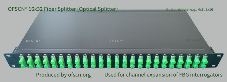
1. OFSCN® Optical Fiber Splitter
OFSCN® Optical Fiber Splitter | Official Link
Typically includes 16x32 splitters, 8x16 splitters, 4x8 splitters, and 32x64 splitters. This device is primarily used with Beijing Dacheng Yongsheng Technology Co., Ltd. demodulators, capable of exponentially expanding physical channels (requiring strict wavelength allocation design), thereby reducing the average cost per channel.
2. OFSCN® Fiber Bragg Grating Interrogator
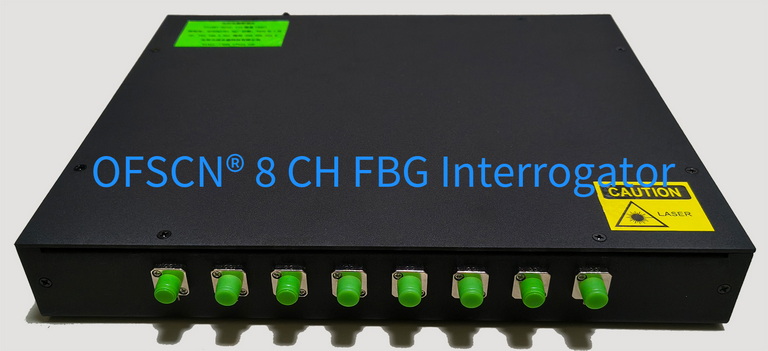
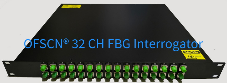
OFSCN® Fiber Bragg Grating Interrogator | Official Link
This equipment features an extremely high optical power dynamic range and wavelength resolution. It supports custom configurations for 4, 8, 16, and 32 channels, with a default wavelength range of 1525\ \text{nm} \sim 1565\ \text{nm} and selectable sampling frequencies of 10\ \text{Hz} \sim 100\ \text{Hz} .
3. OFSCN® Standard Femtosecond Fiber Bragg Gratings
OFSCN® Standard Femtosecond Fiber Bragg Gratings | Official Link
Utilizing femtosecond laser point-by-point writing technology, it does not damage the fiber coating. It provides high-quality, stable reflectivity ( 20\% \sim 70\% ) and excellent side-mode suppression ratio ( \ge 15\ \text{dB} ), suitable for high-loss, long-distance, complex links.
