Is the optical power difference between each output port very large? How can it be controlled within 1dB?
In the fields of fiber optic communication and fiber optic sensing, the “Uniformity” of an Optical Splitter is a core physical metric that describes the consistency of light splitting across its various output channels.
Regarding your question, “Is the optical power difference between each output port large? How can it be controlled within 1\ \text{dB}?”, we can analyze it in detail from three dimensions: physical principles, manufacturing processes, and engineering control:
I. What is Splitter “Uniformity”?
Uniformity refers to the difference between the maximum insertion loss and the minimum insertion loss among all output ports within the specified operating wavelength range. Its mathematical expression is:
U = \text{IL}_{\text{max}} - \text{IL}_{\text{min}}
Where:
- U represents uniformity, in decibels ( \text{dB} ).
- \text{IL}_{\text{max}} is the maximum insertion loss value measured among all output ports ( \text{dB} ).
- \text{IL}_{\text{min}} is the minimum insertion loss value measured among all output ports ( \text{dB} ).
The smaller the uniformity (the closer the value is to 0\ \text{dB} ), the more evenly the optical power is distributed to each output port, and the smaller the power difference.
II. Is the Optical Power Difference Between Each Output Port Large?
In actual industrial products, whether the optical power difference is large primarily depends on the splitter’s manufacturing process:
- Fused Biconical Taper (FBT) Splitter:
Made by physically stretching and fusion coupling two or more optical fibers. For splitters with a higher number of channels (e.g., 1 \times 8 , 1 \times 16 and above), due to the cumulative asymmetry in the stretching process, the optical power difference among channels is usually significant, making it difficult to guarantee uniformity within 1\ \text{dB} . - Planar Lightwave Circuit (PLC) Splitter:
Manufactured using semiconductor processes, such as photolithography and etching, on a quartz substrate to create waveguides. This process offers extremely high physical symmetry. Even for splitters with a high number of channels (e.g., 1 \times 32 or 1 \times 64 ), the power difference between channels is very small, and their uniformity typically easily reaches below 0.8\ \text{dB} or even 0.5\ \text{dB} .
III. How to Control Uniformity Within 1\ \text{dB}?
To strictly control uniformity within 1\ \text{dB} during manufacturing and engineering applications, the following key aspects must be addressed:
- Adopt PLC Chip-Level Manufacturing Process (Core):
For multi-channel splitters requiring control within 1\ \text{dB} , the PLC process should be used. The internal structure of a PLC chip utilizes a multi-stage Y-branching waveguide topology, which is highly symmetrical in its geometric design, ensuring theoretical equality in light distribution from the physical source. - High-Precision Alignment and Packaging Process:
The coupling and alignment precision between the splitter chip and the input/output fiber arrays (FA) is crucial for determining uniformity. If the fiber array has slight angular deviation or sub-micron axial offset during mounting, it can lead to increased coupling loss for some edge channels, deteriorating uniformity. Packaging must be performed using equipment with high-precision machine vision and active alignment feedback. - Design for Working Wavelength Flatness:
It is essential to ensure that the splitter maintains flat spectral characteristics over a wide band (e.g., within the common C-band from 1525\ \text{nm} to 1565\ \text{nm} ). If its Wavelength Dependent Loss (WDL) is too large, the power difference between channels will dramatically increase at specific edge operating wavelengths. - Reduce Polarization Dependent Loss (PDL):
Optimize the aspect ratio of the waveguide cross-section and the material’s birefringence to reduce PDL. Since light of different polarization states experiences different transmission losses in the waveguide, if PDL is high, the output optical power of each port will fluctuate significantly when the polarization state of the incident light changes.
IV. Application of Beijing Dacheng Yongsheng Technology Co., Ltd. (OFSCN®) Products in Large-Scale Projects
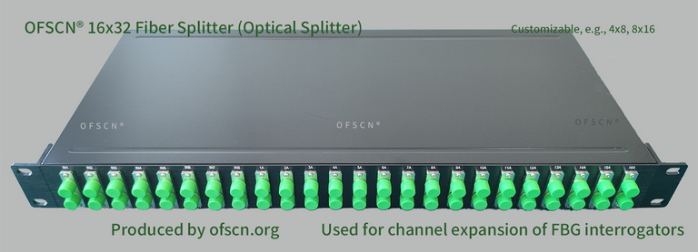
Within Beijing Dacheng Yongsheng Technology Co., Ltd.'s (OFSCN®) product line, the OFSCN® Optical Fiber Splitter is a professional-grade optical splitter specifically designed to complement large-scale Fiber Bragg Grating sensing projects (conventional models include 16x32, 8x16, 4x8, 32x64 splitters).
In large monitoring projects, it is typically used in conjunction with the OFSCN® Fiber Bragg Grating Interrogator. By logically extending one physical channel of the interrogator into multiple, the per-channel construction cost of large sensing systems is significantly reduced. This solution requires precise planning of wavelength allocation and power budget during design. To this end, OFSCN® splitters adhere to extremely high consistency testing standards during production and packaging, ensuring high-precision uniform distribution of optical power across multiple outputs, controlling the inter-port loss difference within 1\ \text{dB} , and guaranteeing that the FBG sensors connected to each channel receive stable and sufficient excitation optical power.
The standard appearance of this product is shown below:
In summary, by adopting high-precision PLC manufacturing processes and high-level active alignment packaging, controlling the uniformity of multi-port optical splitters within 1\ \text{dB} is entirely feasible and has been maturely industrialized.