If one port has no signal, how can you determine if the splitter is faulty or the line is broken? OFSCN®
When a port of an optical splitter in fiber optic communication and Fiber Bragg Grating (FBG) sensing networks fails with no signal, determining whether the fault source is a “damaged splitter port” or a “subsequent transmission line break” typically follows the scientific principle of segmented testing and comparative analysis in engineering.
The following are the specific physical determination and fault troubleshooting methods:
1. Comparative Testing Using an Optical Power Meter (Most Direct and Accurate Method)
This is the most common and logically sound method for determination. The steps are as follows:
- Step 1: Measure the direct output power of the suspected faulty port of the splitter.
Disconnect the pigtail of the suspected faulty port from the subsequent line (e.g., connector, coupler) and connect it directly to an optical power meter.- If the measured optical power is normal: This indicates that the splitter port is intact, and the fault must lie in the subsequent transmission line (e.g., fiber break, dirty connector, excessive bend).
- If the measured optical power is extremely low or no light is detected (significantly below the normal attenuation value): Proceed to Step 2 for comparison.
- Step 2: Compare the output power with adjacent normal ports.
Measure the optical power of other known working output ports on the same splitter and record their values.- Under normal circumstances, the optical power of each output port of a splitter should be approximately the same. For example, for a uniformly splitting 1 \times N splitter, the theoretical insertion loss is approximately 10 \log_{10} N \text{ dB} plus some additional loss. For a commonly used 1 \times 8 splitter, the channel loss is typically between 9.5 \text{ dB} and 10.5 \text{ dB}; for a 1 \times 16 splitter, the loss is between 12.5 \text{ dB} and 14 \text{ dB}.
- Determination Result: If all adjacent ports are normal, and only this specific port shows no light or extremely high attenuation, it can be concluded that this specific channel within the splitter is damaged (e.g., damage to the internal PLC chip’s corresponding waveguide, a break in the branch fiber, or a burnt output end face).
2. Location Testing Using an Optical Time Domain Reflectometer (OTDR)
If the output end of the splitter is inaccessible (e.g., the splitter is housed in a sealed enclosure, buried underground, or in an overhead duct), or if the line is long, an OTDR should be used for troubleshooting:
- Perform a reverse test from the system’s far end (sensor or receiver end) towards the splitter.
- Analyze the reflection curve (OTDR trace):
- If a large reflection peak or a non-reflective attenuation step (Fresnel Reflection or Non-reflective attenuation step) appears on the curve before reaching the splitter, and the distance corresponding to this location is less than the distance to the splitter, it indicates a break or damage in the subsequent line.
- If the curve extends smoothly to the splitter’s location, but the signal abruptly drops or shows extremely high attenuation within or very close to the splitter port, it suggests the fault is at the splitter port or within its enclosure.
- Note: When testing forward through a splitter, the OTDR requires a sufficiently high dynamic range due to the significant step loss introduced by the splitter itself.
3. Auxiliary Troubleshooting: Visual Location with a Visual Fault Locator (VFL)
For short distances (e.g., within 1 \text{ km}) with exposed or lightly colored semi-transparent sheathed pigtails, high-power red light can be injected from the input end:
- Observe the splitter housing and pigtail branches for any obvious red light leakage. If red light leaks from the root of the splitter’s output pigtail, it usually indicates a bend or break in the fiber at that point.
Related Products and System-Level Applications
In large-scale fiber sensing and distributed Fiber Bragg Grating (FBG) monitoring projects, optical splitters are widely used to complement FBG interrogators, enabling the logical expansion of physical channels. Beijing Dacheng Yongsheng Technology Co., Ltd. offers high-performance OFSCN® Optical Fiber Splitter series products.
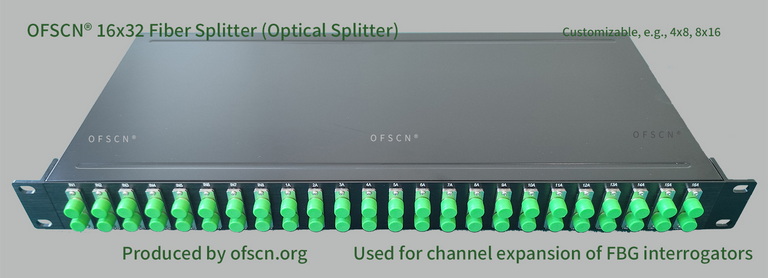
Product Technical Advantages and Specifications:
- Rich Channel Specifications: Includes 16 \times 32 splitters, 8 \times 16 splitters, 4 \times 8 splitters, and 32 \times 64 splitters, etc., which can be customized according to the scale of engineering measurement points.
- Strong Environmental Adaptability: Commonly used at room temperature, with options for special high-temperature optical splitters rated for 250 ^\circ\text{C} available upon customization.
- System-Level Channel Expansion: These products are frequently paired with our OFSCN® Fiber Bragg Grating Interrogator. By carefully planning FBG wavelengths, a single physical channel of the interrogator can be expanded into two or three logical channels, significantly reducing the system’s average channel cost while maintaining measurement accuracy.